A speed bump that can be turned into an isolation pile

A technology of speed bumps and isolation piles, applied in the directions of roads, road signs, traffic signals, etc., can solve the problems of high price, lack of ability to restrict vehicle passing, and lack of deceleration effect, so as to achieve the effect of blocking function and avoiding damage.

Pending Publication Date: 2019-01-25
SHANDONG UNIV OF SCI & TECH
View PDF6 Cites 6 Cited by
  • Summary
  • Abstract
  • Description
  • Claims
  • Application Information

AI Technical Summary

Problems solved by technology

[0002] Nowadays, the use of speed bumps is particularly widespread, and the functions of speed bumps are more diverse. Speed ​​bumps are safety devices, which are mainly installed on roads, units, and company gates to reduce the speed of motor vehicles, etc.; and automatic isolation piles belong to the passageway Control equipment, mainly used for traffic, landscape, public parking spaces, etc. to close the passage intersections in designated areas, with anti-collision and anti-riot functions; isolation piles can block the passage of motor vehicles, but the price is high, and they do not have any deceleration effect; on the contrary , the deceleration belt effectively reduces the speed of motor vehicles, etc., but does not have the ability to restrict the passing of vehicles; therefore, the existing technology needs further improvement and development

Method used


Image

  • A speed bump that can be turned into an isolation pile
  • A speed bump that can be turned into an isolation pile
  • A speed bump that can be turned into an isolation pile

Examples


Embodiment Construction

[0022] The present invention provides a deceleration belt that can be turned into an isolation pile. In order to have a clearer understanding of the purpose and effect of the present invention, the technical solution of the present invention will be further described below in conjunction with the accompanying drawings in the examples of the present invention; The embodiments of the present invention and all other embodiments obtained by persons of ordinary skill in the art without making creative efforts belong to the protection scope of the present invention.

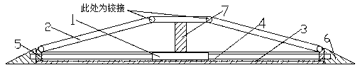
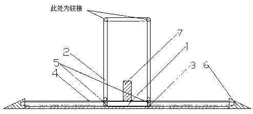
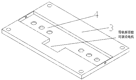
[0023] Such as Figure 1-7 As shown, the present invention provides a deceleration belt that can be turned into an isolation pile, mainly including a driving device 1, a trapezoidal foldable combined deceleration belt 2, a guide rail plate 3, a guide groove 4, a slider 5, and a triangular baffle 6 , support block 7 etc.; described driving device 1 is mainly made up of screw mandrel 8, motor 9, worm wheel 10, worm screw...


PUM


Abstract

The invention discloses a speed reduction belt which can be turned into an isolation pile, comprising a driving device, a trapezoidal foldable combined speed reduction belt, a guide rail plate, a guide groove, a slide block, a triangular baffle plate, a support block and the like; the speed reduction belt comprises a driving device and a trapezoidal foldable combined speed reduction belt. The bottom plate of the speed reduction belt is mainly composed of a guide rail plate, a guide groove and a triangular baffle plate, wherein the guide groove is arranged in the guide rail plate, and the triangular baffle plate is arranged at both ends of the guide rail plate. The two inclined surfaces of the speed reduction belt are articulated with the top surface, the inclined surface can rotate aroundthe top surface, the bottom end of the inclined surface is articulated with the slider, the slider is connected with the driving device, and the slider can slide in the guide groove. The device normally is a trapezoidal speed-down belt. If it is necessary to block the passage of a motor vehicle, the driving device controls the speed-down belt to slide in the middle of two oblique faces, and can beused as an isolation pile when the top plate is lifted and the side surface is vertical. The driving device controls the speed-down belt to slide on both oblique faces, and then the speed-down belt can be changed back. The device can be installed in the road section, in front of the unit door and other positions, and can play the function of decelerating and blocking the motor vehicle.

Description

technical field [0001] The invention belongs to the technical field of traffic management facilities, and in particular relates to a speed bump that can be turned into an isolation pile. Background technique [0002] Nowadays, the use of speed bumps is particularly widespread, and the functions of speed bumps are more diverse. Speed ​​bumps are safety devices, which are mainly installed on roads, units, and company gates to reduce the speed of motor vehicles, etc.; and automatic isolation piles belong to the passageway Control equipment, mainly used for traffic, landscape, public parking spaces, etc. to close the passage intersections in designated areas, with anti-collision and anti-riot functions; isolation piles can block the passage of motor vehicles, but the price is high, and they do not have any deceleration effect; on the contrary , the deceleration belt effectively reduces the speed of motor vehicles, etc., but does not have the ability to limit the passing of vehic...

Claims


Application Information

Patent Timeline
Patent Type & Authority Applications(China)
IPC IPC(8): E01F9/529E01F13/04
CPCE01F9/529E01F13/046
Inventor 王树凤袁亚东刘哲崔国臣李志豪王永庆
Owner SHANDONG UNIV OF SCI & TECH
Why Eureka
Try Eureka