
A multi-layer partition drying device

A technology of drying device and drying layer, applied in drying, drying machine, drying gas arrangement and other directions, can solve the problems of difficult operation and high time cost, so as to increase drying area, improve efficiency and reduce heat uneven effect

Active Publication Date: 2020-09-29
睢宁长青生物质能源有限公司
View PDF5 Cites 0 Cited by
  • Summary
  • Abstract
  • Description
  • Claims
  • Application Information

AI Technical Summary

Problems solved by technology

[0002] The crops and materials are generally dried after harvesting. In the prior art, a single drying device is mostly used for drying crops and materials. The purpose of drying is to meet the needs of material use or further processing. The existing drying The device generally adopts a drying box, in which a charging device is installed, and a heating device is set to heat the material. However, each crop or material is dried to the desired state, and the heating time and drying air flow are different according to the type. Different, therefore, when it is necessary to dry multiple materials at the same time, it is often necessary to dry one type, and then replace other materials for adjustment. The drying technology in the prior art cannot meet the simultaneous drying of multiple materials, and targeted drying. Therefore, it has the problems of high time cost and difficult operation. Even for the same crop, according to the refinement of food and classification, there are also needs for different drying degrees. Therefore, the drying device in the prior art cannot efficiently achieve different drying degrees. product needs

Method used


Image

  • A multi-layer partition drying device
  • A multi-layer partition drying device
  • A multi-layer partition drying device

Examples


Embodiment Construction

[0022] The following will clearly and completely describe the technical solutions in the embodiments of the present invention with reference to the accompanying drawings in the embodiments of the present invention. Obviously, the described embodiments are only some, not all, embodiments of the present invention. Based on the embodiments of the present invention, all other embodiments obtained by persons of ordinary skill in the art without making creative efforts belong to the protection scope of the present invention.

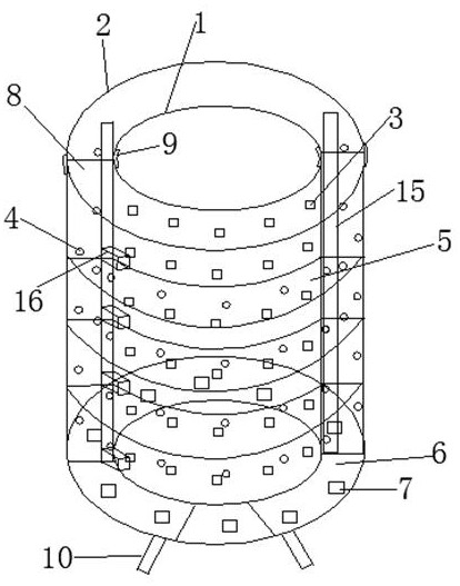
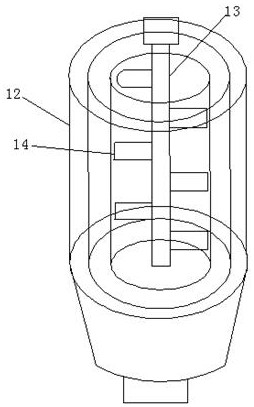
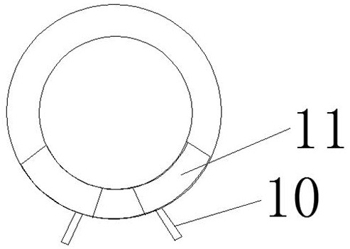
[0023] refer to Figure 1-4 : A multi-layer drying device, comprising a drying inner cylinder 1, a drying outer cylinder 2, and a bottom plate 6, both of the drying inner cylinder 1 and the drying outer cylinder 2 are hollow, and the outer circumference of the drying inner cylinder 1 is A plurality of heat transfer holes 3 are provided, and a plurality of heat dissipation holes 3 are provided on the peripheral outer wall of the drying outer cylinder 2. The spa...


PUM


Abstract

The invention discloses a multi-layer region dividing drying device. The device comprises a drying inner tube, a drying outer tube and a bottom plate. The drying inner tube and the drying outer tube are hollowed, longitudinal region diving of crops can be achieved by the arrangement of multi-layer drying chambers, an adopted heating device combining with the drying device has multiple layers, theheating temperature is targetedly adjusted for crops in each layer to achieve different heating effect, crops with different dryness can be obtained, time cost is reduced, a rotary type heating deviceis adopted, the problem which might takes place of nonuniform heat in constant heating process is reduced, an annular material chamber has the effect of increasing the drying area compared with a conventional drying plate, the efficiency can be improved, longitudinal region dividing can be achieved by vertical separation plates, and the material amount of each longitudinal divided region can be adjusted according to demands.

Description

technical field [0001] The invention relates to the technical field of drying, in particular to a layered drying device. Background technique [0002] The crops and materials are generally dried after harvesting. In the prior art, a single drying device is mostly used for drying crops and materials. The purpose of drying is to meet the needs of material use or further processing. The existing drying The device generally adopts a drying box, in which a charging device is installed, and a heating device is set to heat the material. However, each crop or material is dried to the desired state, and the heating time and drying air flow are different according to the type. Different, therefore, when it is necessary to dry multiple materials at the same time, it is often necessary to dry one type, and then replace other materials for adjustment. The drying technology in the prior art cannot meet the simultaneous drying of multiple materials, and targeted drying. Therefore, it has ...

Claims


Application Information

Patent Timeline
Patent Type & Authority Patents(China)
IPC IPC(8): F26B9/06F26B21/12
CPCF26B9/06F26B21/12
Inventor 李春威
Owner 睢宁长青生物质能源有限公司
Learn More