Method and device for measuring wear of catenary wire

A catenary and wire technology, which is applied to measuring devices, optical devices, instruments, etc., can solve the problems of large impulse, large wear of contact wires, and inflexibility of rigid suspension busbars, so as to achieve easy maintenance and replacement, easy expansion, The effect of easier and more intuitive monitoring of wear

Active Publication Date: 2020-03-20
CHENGDU TANGYUAN ELECTRICAL APPLIANCE
View PDF5 Cites 2 Cited by
  • Summary
  • Abstract
  • Description
  • Claims
  • Application Information

AI Technical Summary

Problems solved by technology

The rigid suspension busbar has no elasticity and is used to counteract the lifting force of the pantograph. It suddenly appears with the lifting force of the pantograph on the contact suspension, so that the impulse of the pantograph lifting force to the contact suspension is relatively large. Thus the wear of the contact wire is greater

Method used


Image

  • Method and device for measuring wear of catenary wire
  • Method and device for measuring wear of catenary wire
  • Method and device for measuring wear of catenary wire

Examples


Embodiment 1

[0057] A catenary wire wear measurement method comprising:

[0058] Step 1 (image collection step): n road cameras correspondingly collect n pieces of catenary wire images including the bottom of the catenary wire located in different pull-out value ranges; n is greater than or equal to 1;

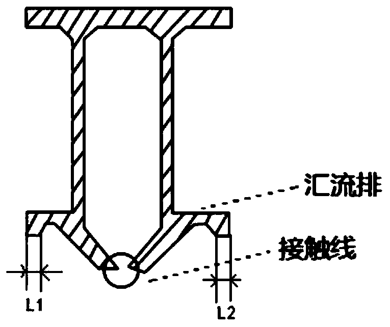
[0059] Among them, when the wear measurement requires detection of the pull-out value range beyond the effective pull-out value range of the single-channel image acquisition camera, the L2 width information cannot be recognized, and the wire wear value d cannot be calculated, and it is judged whether the single image is caused by The L1 line segment, L2 line segment, and L3 line segment do not exist locally; then, n-channel cameras are used to collect the wire images in different pull-out value ranges, and the pull-out value distribution has a certain range of overlapping intervals. Fusion is mainly responsible for merging and correlating the positions of the wires in the images captured b...

Embodiment 2

[0082] Embodiment 2: when the wear value calculation step cannot calculate the wire wear value d, then after the wire positioning step, the wire contour tracking step is also included before the wear value calculation step (then first, the wire position fusion is performed on the n-way camera images to obtain The position information of the wire in different camera images, and then the wire tracking process is performed to compensate for the wire breakage in the image caused by the complexity of the line, and finally after the complete position information of L1, L2 and L3 is obtained by tracking, the wire wear value is identified and calculated) , (this step is suitable for n=1, also suitable for n greater than or equal to 2), specifically:

[0083] Step 51: refine the central positions of L1, L2 and L3;

[0084] Step 52: On the basis of the maximum connected domain of the wires, the center positions of L1, L2, and L3 are combined with the boundary positions E1 and E2 to iden...


PUM


Abstract

The invention relates to the field of measurement of a rigid conductor of an overhead contact system of a subway system in urban mass transit, in particular to a method and a device for measuring abrasion of an overhead contact system conductor. According to the scheme, the method comprises the following steps of determining the number n of cameras according to the range of pull-out values of contact lines; correspondingly collecting n overhead contact system conductor images comprising overhead contact system conductor bottoms by n paths of cameras, wherein n is larger than or equal to 1; correspondingly segmenting n maximum conductor connected regions comprising L1, L2 and L3, n boundary positions E1 and n boundary positions E2 from the n overhead contact system conductor images; obtaining n thresholding images T(x, y) based on thresholding processing of the n maximum conductor connected regions; respectively correspondingly combining the n thresholding images T(x, y) with n boundarypositions E1 and n boundary positions E2 according to the characteristics of the connected regions in order to obtain n pieces of position information of L1, L2 and L3; and computing a conductor abrasion value d by utilizing the positioning information of the conductor L2.

Description

technical field [0001] The invention relates to the field of measuring the rigid wire of a catenary system in a metro system in urban rail transit, in particular to a method and a device for measuring the wear of a catenary wire. Background technique [0002] In the electrified railway, the electric locomotive obtains electric energy from the catenary through the pantograph, and the contact line is deformed, vibrated and caused alternating stress changes, locomotive running mode, current intake state and other factors to wear the contact line, when the wear surface When it reaches a certain level, it will lead to disconnection. [0003] During the running of the train, the current is taken through the sliding contact between the pantograph slide plate and the contact wire. To make the pantograph receive current well, it is necessary to ensure reliable contact between the pantograph slide plate and the contact wire, which requires a certain contact pressure between the panto...

Claims


Application Information

Patent Timeline
Patent Type & Authority Patents(China)
IPC IPC(8): G01B11/02
CPCG01B11/022
Inventor 李想佘朝富陈唐龙王瑞锋于龙彭博曹伟冷强兵陈洪友沈昌武舒熊王秋莲刘华云
Owner CHENGDU TANGYUAN ELECTRICAL APPLIANCE
Why Eureka
Try Eureka