A method and device for measuring the wear of catenary wires based on machine vision
A technology of machine vision and measurement methods, applied in the direction of measuring devices, optical devices, instruments, etc., can solve the problems of rigid suspension busbars such as inelasticity, large impulse, and large degree of wear of contact wires, so that the wear situation is easier to monitor intuitively, Overcome all kinds of interference and facilitate timely feedback on the effect of maintenance and replacement
- Summary
- Abstract
- Description
- Claims
- Application Information
AI Technical Summary
Problems solved by technology
Method used
Image
Examples
Embodiment 1
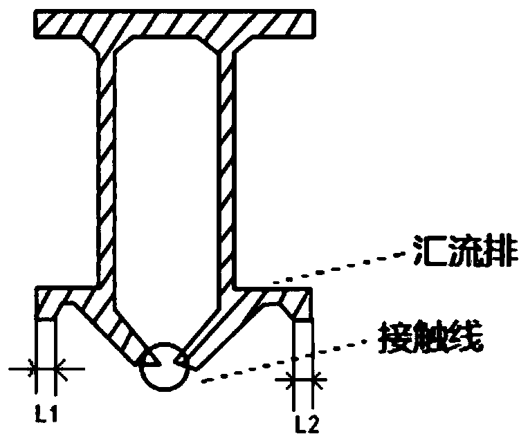
[0051] Step 1: Single-channel camera captures the catenary image including the bottom of the catenary rigid conductor;
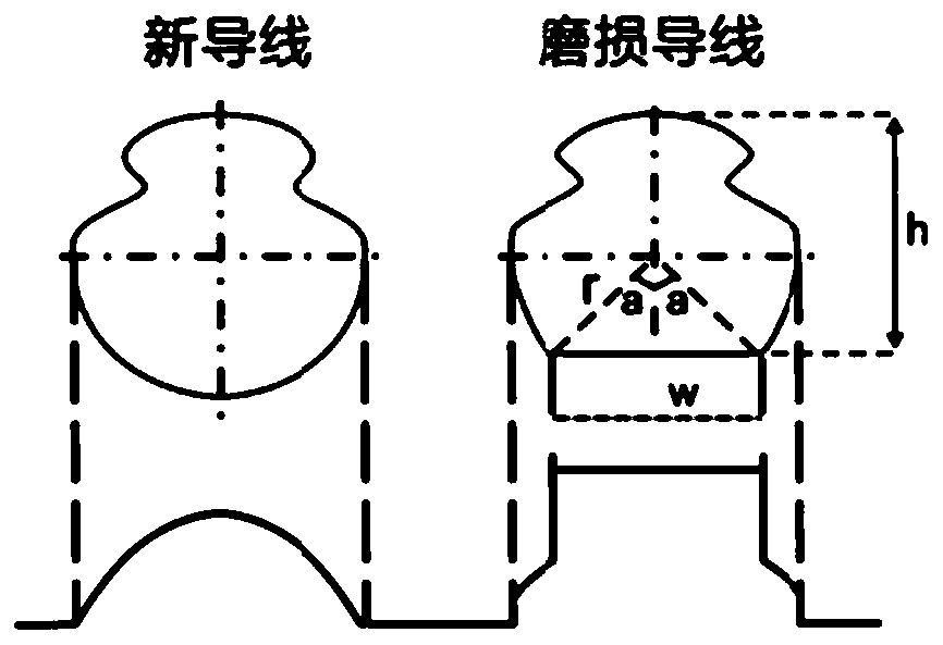
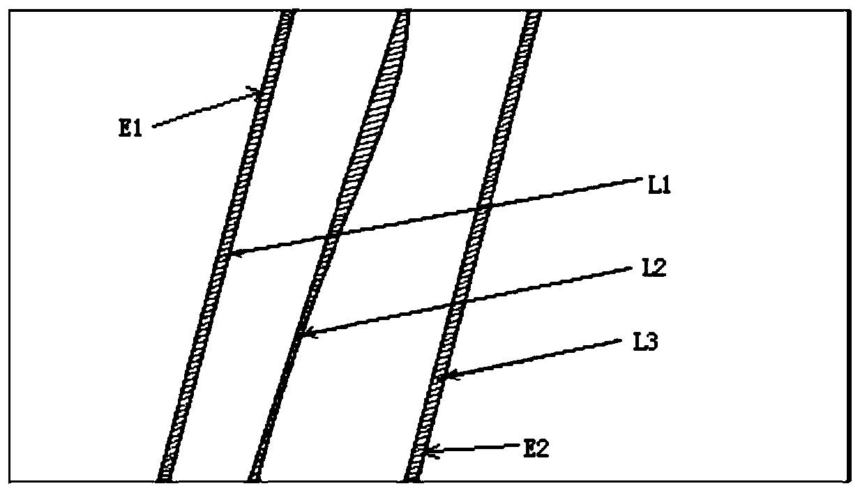
[0052] Step 2: Segment the maximum connected area of catenary wires including L1, L2 and L3, boundary position E1 and boundary position E2 from the above-mentioned catenary image;
[0053] Step 2. The specific process of segmenting the maximum connected area, boundary position E1 and boundary position E2 of the wire is: according to the general gray distribution characteristics of catenary wire imaging, by setting the empirical threshold, the maximum connected area of the wire including L1, L2 and L3 Distinguished from the background area, the maximum connected area of the wire including L1, L2 and L3 is obtained.
[0054] Step 3: Thresholding the maximum connected area of the catenary wire to obtain the thresholded image T(x, y). According to the characteristics of the connected area of the catenary wire, combined with the boundary position E1 and...
Embodiment 2
[0066] Embodiment 2: On the basis of Embodiment 1, when the L2 width information cannot be identified through one image acquisition camera, and the wire wear value d cannot be calculated, it is necessary to further determine whether the single image is due to the L1 and L2 in the image. The L3 wire is discontinuous; the specific steps are:
[0067] Step 5: When the wire wear value d cannot be calculated, it also includes:
[0068] Step 51: Refine the central positions of L1, L2 and L3; that is, on the basis of the calculated L1, L2 and L3 and the bus boundary E1 and E2, use the binary image refinement algorithm to determine the maximum connectivity of L1, L2 and L3 The area is refined, and the three centerlines corresponding to L1, L2 and L3 can be obtained;
[0069] Step 52: On the basis of the maximum connected domain of the wires, the center positions of L1, L2, and L3 are combined with the left and right borders E1, E2 of the wires to identify the discontinuity of the wir...
PUM
 Abstract
Description
Claims
Application Information
 - R&D
- Intellectual Property
- Life Sciences
- Materials
- Tech Scout
- Unparalleled Data Quality
- Higher Quality Content
- 60% Fewer Hallucinations
Browse by: Latest US Patents, China's latest patents, Technical Efficacy Thesaurus, Application Domain, Technology Topic, Popular Technical Reports.
© 2025 PatSnap. All rights reserved.Legal|Privacy policy|Modern Slavery Act Transparency Statement|Sitemap|About US| Contact US: help@patsnap.com


