a see-through device
A one-way perspective, liquid crystal technology, used in instruments, nonlinear optics, optics, etc., can solve the problems of fixed light transmittance, inability to adjust and control, etc.
- Summary
- Abstract
- Description
- Claims
- Application Information
AI Technical Summary
Problems solved by technology
Method used
Image
Examples
no. 1 example
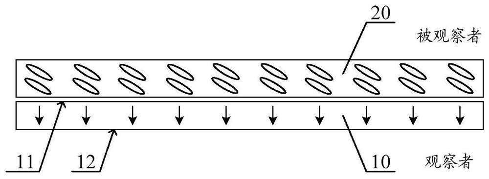
[0049] figure 1 It is a structural schematic diagram of the see-through device according to the first embodiment of the present invention. The see-through device has a side facing the observer and a side facing the person being observed. The one-way see-through layer 10 has a first face 11 towards the observed side and a second face 12 towards the observed side, and the one-way see-through direction of the one-way see-through layer 10 is from the observed side towards the observer One side (that is, from the first surface 11 to the second surface 12). In this embodiment, the liquid crystal control layer includes a first liquid crystal control layer 20 . The first liquid crystal adjusting layer 20 is stacked with the one-way see-through layer 10 , and the first liquid crystal adjusting layer 20 is set on the side of the one-way see-through layer 10 facing the observed person. In other embodiments, the first liquid crystal regulating layer 20 may also be disposed on the side ...
no. 2 example
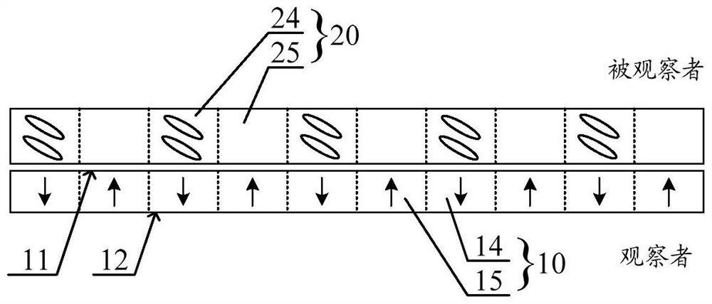
[0056] image 3 It is a structural schematic diagram of the see-through device according to the second embodiment of the present invention. Different from the first embodiment, in this embodiment, if image 3 As shown, the first liquid crystal adjustment layer 20 has a first adjustment area 24 and a first blank area 25, and the liquid crystal molecules are arranged in the first adjustment area. The one-way see-through layer 10 has a first see-through area 14 and a second see-through area 15 . The first see-through area 14 has a one-way see-through function from the observed side to the observer's side, and the second see-through area 15 has a one-way see-through function from the observer's side to the observed side. In this embodiment, there is an overlapping area between the first adjustment area 24 and the first see-through area 14 , and an overlapping area between the first blank area 25 and the second see-through area 15 .
[0057] In the see-through device of the embo...
no. 3 example
[0067] Image 6 It is a structural schematic diagram of the see-through device according to the third embodiment of the present invention. Different from the second embodiment, in this embodiment, the see-through device may also include a second liquid crystal adjusting layer 30, and the second liquid crystal adjusting layer 30, the one-way see-through layer 10 and the first liquid crystal adjusting layer 20 are laminated set up. In this embodiment, the second liquid crystal adjustment layer 30 and the first liquid crystal adjustment layer 20 are respectively disposed on opposite sides of the one-way perspective layer 10 .
[0068] In the see-through device of this embodiment, the second liquid crystal adjustment layer 30 can be used to assist in adjusting the light transmittance of the see-through device from the observed side to the observer's side to obtain better brightness adjustment. At the same time, the second liquid crystal adjustment layer 30 can also be used to ad...
PUM
 Abstract
Description
Claims
Application Information
 - R&D
- Intellectual Property
- Life Sciences
- Materials
- Tech Scout
- Unparalleled Data Quality
- Higher Quality Content
- 60% Fewer Hallucinations
Browse by: Latest US Patents, China's latest patents, Technical Efficacy Thesaurus, Application Domain, Technology Topic, Popular Technical Reports.
© 2025 PatSnap. All rights reserved.Legal|Privacy policy|Modern Slavery Act Transparency Statement|Sitemap|About US| Contact US: help@patsnap.com


