
A two-degree-of-freedom bearingless permanent magnet motor

A permanent magnet motor, bearingless technology, used in electrical components, electromechanical devices, electric components, etc., can solve the problem of difficult to install auxiliary bearings, achieve continuous control, easy operation, and reduce start-up shocks.

Inactive Publication Date: 2019-01-25
ZHENJIANG YUANDONG ELECTRIC MOTOR +1
View PDF0 Cites 0 Cited by
  • Summary
  • Abstract
  • Description
  • Claims
  • Application Information

AI Technical Summary

Problems solved by technology

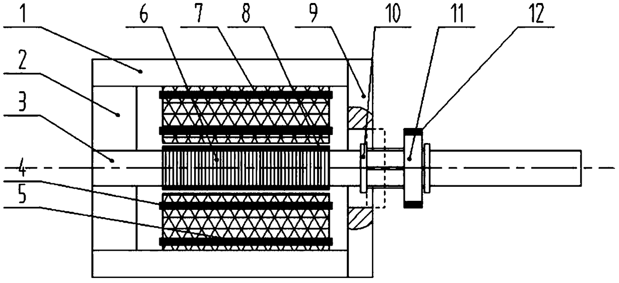
[0006] According to the deficiencies and defects of the prior art, the present invention proposes a two-degree-of-freedom bearingless permanent magnet motor, the purpose of which is to overcome the problem that it is difficult to install an auxiliary bearing in an unideal environment for a two-degree-of-freedom bearingless motor

Method used


Image

  • A two-degree-of-freedom bearingless permanent magnet motor
  • A two-degree-of-freedom bearingless permanent magnet motor
  • A two-degree-of-freedom bearingless permanent magnet motor

Examples


Embodiment Construction

[0021] In order to make the object, technical solution and advantages of the present invention clearer, the present invention will be further described in detail below in conjunction with the accompanying drawings and embodiments. It should be understood that the specific embodiments described here are only used to explain the present invention, not to limit the present invention.

[0022] In describing the present invention, it is to be understood that the terms "radius", "upper", "lower", "left", "right", "top", "bottom", "inner", "outer" etc. indicate The orientation or positional relationship is based on the orientation or positional relationship shown in the drawings, and is only for the convenience of describing the present invention and simplifying the description, rather than indicating or implying that the referred device or element must have a specific orientation or be configured in a specific orientation. and operation, and therefore should not be construed as limi...


PUM


Abstract

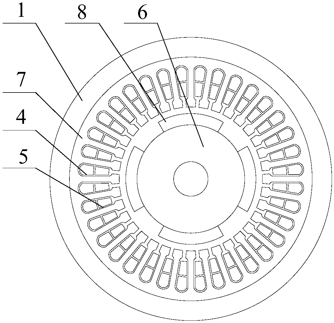
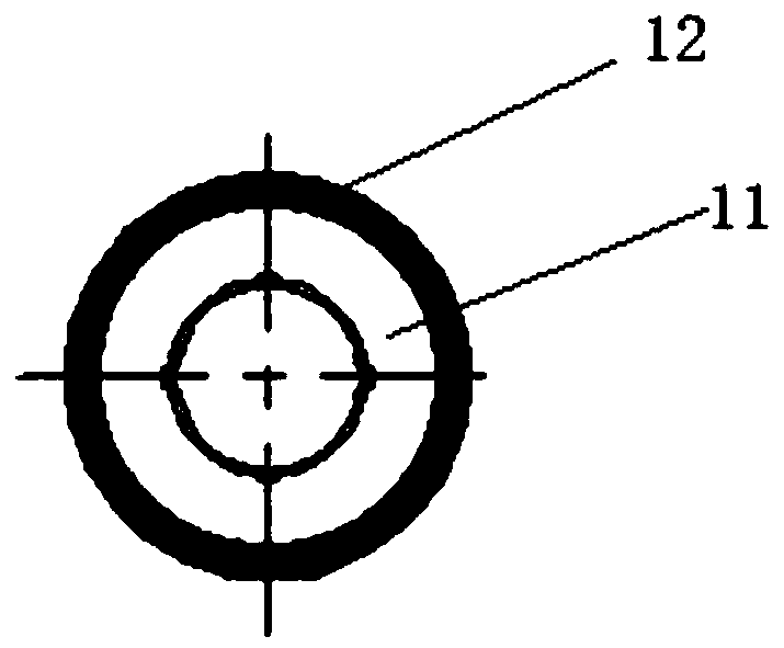
The invention discloses a two-degree-of-freedom bearingless permanent magnet motor, which comprises a mechanical rotating shaft, a rotor, a stator and a motor frame. The rotor is mounted on the mechanical rotating shaft, and a permanent magnet is attached to the outer surface of the rotor. The stator is sleeved outside the rotor and coaxially arranged with the rotor. The stator is uniformly provided with two layers of through slots in the circumferential direction. The inner layer of through slots is provided with torque windings and the outer layer of through slots is provided with suspensionwindings. One end of the mechanical rotating shaft is provided with a mechanical bearing, and the mechanical bearing is matched with the inner ring of the motor frame; the other end of the mechanicalrotating shaft is provided with a motor end cover, and the motor end cover is connected with the motor frame; 2 circular retain rings are arrange on that mechanical rotating shaft, A convex track isuniformly arranged on a mechanical rotating shaft between two circular retaining rings, and a linear motor is sleeved on the convex track. The invention can have a more novel design of a bearingless permanent magnet motor auxiliary bearing structure, which is inconvenient to add auxiliary bearings manually when the motor stops working, and the control is simpler. The invention is characterized inthat the mechanical rotating shaft is uniformly provided with a convex track and a linear motor is sleeved on the convex track.

Description

technical field [0001] The invention belongs to the technical field of motor equipment, in particular to a two-degree-of-freedom bearingless permanent magnet motor. Background technique [0002] When the two-degree-of-freedom bearingless permanent magnet motor stops working, it usually needs to put on auxiliary bearings to ensure that the rotor is in the center position, which is convenient for system stability and control. Bearingless permanent magnet motors are mostly used in high-pollution, toxic or sealed environments, and it is not convenient to manually add auxiliary bearings when stopping work, which limits their use. Therefore, it is urgent to design an auxiliary bearing structure for a two-degree-of-freedom bearingless permanent magnet motor. [0003] Generally, when the bearingless permanent magnet motor stops working, the mechanical shaft will be shifted from the center position by gravity, causing the motor to return to the original position by controlling the s...

Claims


Application Information

Patent Timeline
Patent Type & Authority Applications(China)
IPC IPC(8): H02K5/16H02K7/12
CPCH02K5/161H02K7/12
Inventor 陆宝富季佳磊朱春霞陶杰赵茜张玉贵
Owner ZHENJIANG YUANDONG ELECTRIC MOTOR
Learn More