
A seismic communication tower

A communication tower and tower body technology, which is applied in the field of seismic communication towers, can solve the problems of poor seismic performance of communication towers, tilted tower bodies, hidden safety hazards, etc., and achieve the effects of enhancing stability and reliability, improving wind resistance and seismic resistance, and reducing vibration.

Active Publication Date: 2020-08-25
STATE GRID JIANGSU ELECTRIC POWER CO LIANYUNGANG POWER SUPPLY CO +1
View PDF1 Cites 1 Cited by
  • Summary
  • Abstract
  • Description
  • Claims
  • Application Information

AI Technical Summary

Problems solved by technology

[0003] Most of the existing communication towers are rigidly connected between the tower body and the base, so in the case of strong wind or earthquake, affected by the wind or earthquake, the force on the connection between the tower body and the base is very large, and the rigidity There is no buffer space between the connected tower body and the base, which poses a safety hazard
[0004] In order to solve the problem of poor seismic performance of communication towers, Chinese patent (CN206722511U) discloses a communication tower with strong seismic function. On the stable block at the lower end of the ground to enhance the anti-seismic ability of the communication tower, but because the tower body and the base are rigidly connected, only the steel wire rope is used for buffering and shock absorption, which may easily cause the tower body to tilt

Method used


Image

  • A seismic communication tower
  • A seismic communication tower
  • A seismic communication tower

Examples


Embodiment Construction

[0022] The technical solution of this patent will be further described in detail below in conjunction with specific embodiments.

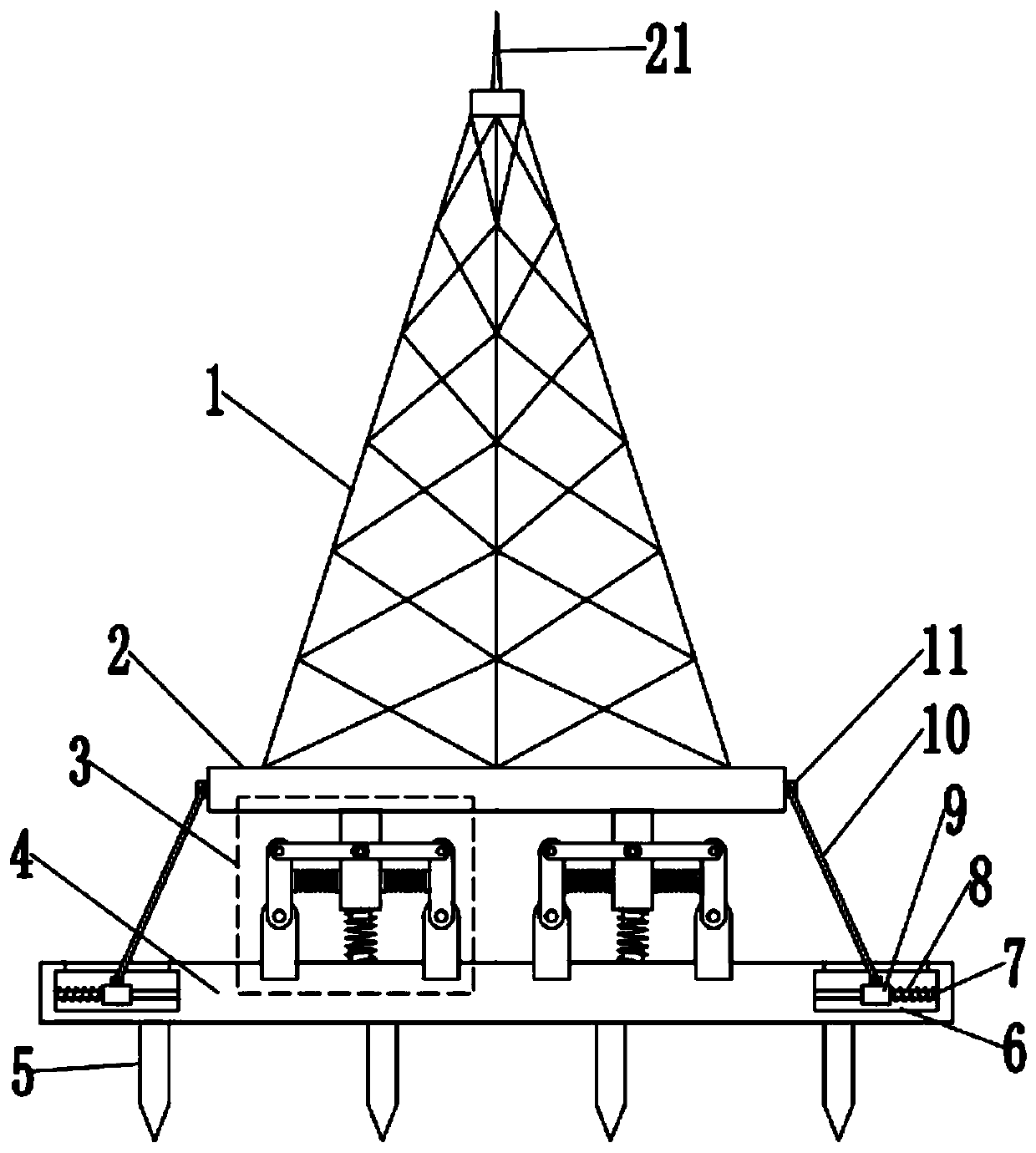
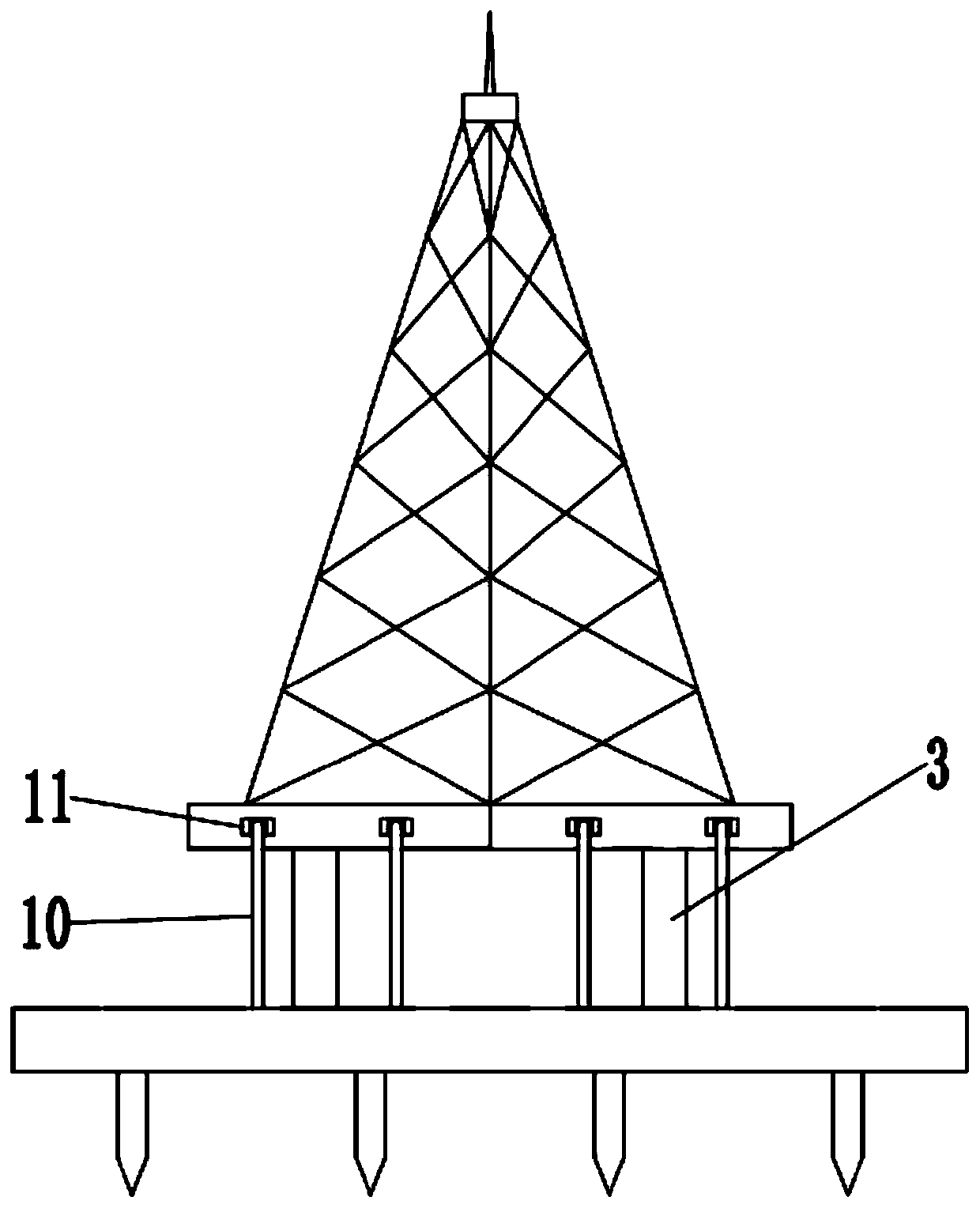
[0023] see figure 1 with figure 2 , an anti-seismic communication tower, comprising a tower body 1, a lightning rod 21 is fixedly installed on the top of the tower body 1, which plays the role of lightning protection, a tower base 2 is fixedly installed on the bottom of the tower body 1, and a shock absorbing device is installed at the bottom of the tower base 2 3. The base 4 is fixedly installed on the bottom of the shock absorbing device 3, and the bottom of the base 4 is fixedly connected with a fixed pile 5. The fixed pile 5 is driven below the ground to ensure the stability of the base 4. There are cavities 6 on both sides of the base 4. The cavity 6 is fixedly connected with a fixed rod 7, the outer side of the fixed rod 7 is covered with a first spring 8, the first spring 8 is fixedly connected with a slider 9 on the inner side, the slider...


PUM


Abstract

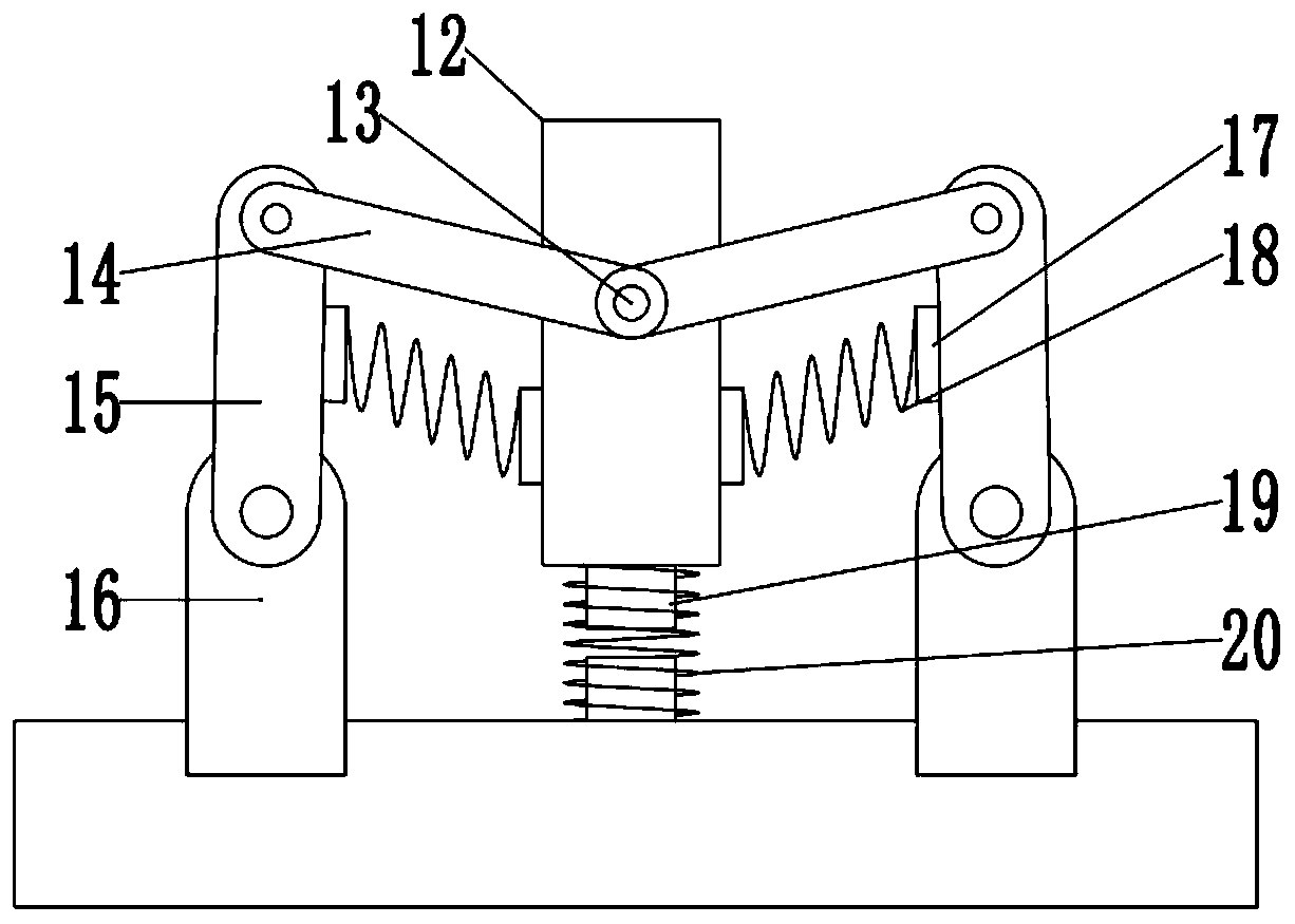
The invention discloses an anti-shock communication tower. The anti-shock communication tower comprises a tower body. A tower seat is fixedly mounted at the bottom of the tower body. Shock absorptiondevices are arranged at the bottom of the tower seat. The shock absorption devices comprise main rods. Protruding columns are fixedly connected to the front sides of the main rods. The protruding columns are rotatably connected with second connecting rods. The second connecting rods are rotatably connected with third connecting rods. The third connecting rods are rotatably connected with fixing seats. Spring seats are fixedly connected to the inner sides of the third connecting rods and the outer sides of the main rods. Second springs are fixedly connected between the spring seats. Spring columns are fixedly connected to the bottoms of the main rods. Third springs sleeve the spring columns. Fixing piles are driven into the ground, and therefore the base is fixed. During shock, the second and third springs of the shock absorption devices are stretched and extruded, and restoring force is generated, and therefore shock to the tower body is obviously reduced. Meanwhile, the first springson two sides of the tower body also generate restoring force, and the tower body is driven to be stable. Wind and shock resisting ability of the tower body is improved, and stability and reliability of the communication tower are improved.

Description

technical field [0001] The invention relates to a communication device, in particular to an anti-seismic communication tower. Background technique [0002] The communication tower is a kind of signal transmission tower, also called a signal transmission tower or a signal tower. Its main function supports signal transmission and supports the signal transmission antenna. Use Mobile / China Unicom / traffic satellite positioning system (GPS) and other communication departments. The communication tower is composed of steel components such as tower body, platform, lightning rod, ladder, antenna support, etc., and has been treated with hot-dip galvanized anti-corrosion treatment. It is mainly used for transmission and emission of microwave, ultrashort wave, and wireless network signals. [0003] Most of the existing communication towers are rigidly connected between the tower body and the base, so in the case of strong wind or earthquake, affected by the wind or earthquake, the f...

Claims


Application Information

Patent Timeline
Patent Type & Authority Patents(China)
IPC IPC(8): E04H12/22
CPCE04H12/2253
Inventor 刘莉
Owner STATE GRID JIANGSU ELECTRIC POWER CO LIANYUNGANG POWER SUPPLY CO
Learn More