
Plasma sound box

A plasma and audio technology, applied in transducer circuits, frequency/direction characteristic devices, sensors, etc., can solve problems such as high technical level, high implementation cost, and complex implementation

Inactive Publication Date: 2019-01-29
HEFEI UNIV OF TECH
View PDF8 Cites 0 Cited by
  • Summary
  • Abstract
  • Description
  • Claims
  • Application Information

AI Technical Summary

Problems solved by technology

However, the implementation of this kind of plasma sound is relatively complicated, and at the same time amplifying the audio signal to the level of kilovolts and maintaining the linearity of the signal requires a high level of technology, and the implementation cost is expensive

Method used


Image

  • Plasma sound box
  • Plasma sound box

Examples


Embodiment Construction

[0022] Embodiments of the present invention will be further described below in conjunction with the accompanying drawings.

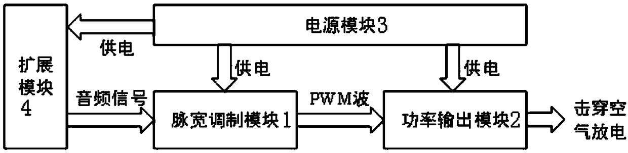
[0023] Please see attached figure 1 and attached figure 2 As shown, a plasma audio system includes a pulse width modulation module 1, a power output module 2, a power supply module 3 and an expansion module 4; the expansion module 4 outputs an audio signal and communicates with the input terminal of the pulse width modulation module 1 connection, the output end of the pulse width modulation module 1 is connected to the input end of the power output module 2, the power supply module 3 is a three-terminal integrated voltage regulator 7805, and is the pulse modulation module 1, power Output module 2 and expansion module 4 supply power.

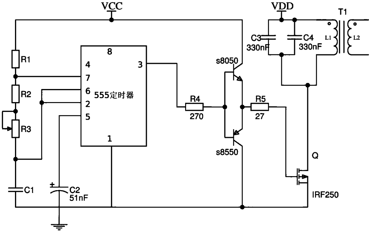
[0024] The pulse modulation module 1 includes a 555 timer; pin 1 of the 555 timer is connected to capacitor C1, capacitor C4 and ground, pin 2 and pin 6 of the 555 timer are connected to the other end of capacitor C1 and...


PUM


Abstract

The invention discloses a plasma sound box, which comprises a pulse width modulation module, a power output module, a power supply module and an expansion module, wherein the expansion module outputsaudio signals and is connected with the input terminal of the pulse width modulation module, the output terminal of the pulse width modulation module is connected with the input terminal of the poweroutput module, and the power supply module is a three terminal-integrated voltage regulator 7805 and provides power for the pulse modulation module, the power output module and the expansion module.

Description

technical field [0001] The invention relates to the technical field of plasma audio, in particular to a plasma audio. Background technique [0002] At present, the existing traditional mechanical speakers generally cause the vibration of the diaphragm to cause air vibration to produce sound, but the diaphragm has a certain quality, which leads to distortion of the sound effect. It cannot meet the needs of most music lovers and special people. Therefore, some audio systems use linear power amplification for the audio signal to make the voltage level of the audio signal reach the kilovolt level, and this voltage is directly loaded on the electrode, and then the electrode is driven to discharge, and the arc disturbs the air to form a sound wave. However, the implementation of this kind of plasma sound is relatively complicated, and at the same time, amplifying the audio signal to the level of kilovolts and maintaining the linearity of the signal requires a high level of techno...

Claims


Application Information

Patent Timeline
IPC IPC(8): H04R1/20H04R3/00
CPCH04R1/20H04R3/00H04R2420/03
Inventor 吴佳卓
Owner HEFEI UNIV OF TECH
Features
  • Generate Ideas
  • Intellectual Property
  • Life Sciences
  • Materials
  • Tech Scout
  • Unparalleled Data Quality
  • Higher Quality Content
  • 60% Fewer Hallucinations
Learn More