Sound box structure

Inactive Publication Date: 2009-11-26
HON HAI PRECISION IND CO LTD
View PDF32 Cites 28 Cited by
  • Summary
  • Abstract
  • Description
  • Claims
  • Application Information

AI Technical Summary

Problems solved by technology

Due to low rigidity thereof, deformation is generated during operation, which decreases the quality of the low frequency sound.
However, such reinforcing ribs not only complicate the sound box structure, but also reduce the resonance chamber in the shell, affecting low frequency reproduction.
In addition, the plastic shell is easily desiccated, shrunk and deformed during the injection molding fabrication process, wh

Method used


Image

  • Sound box structure
  • Sound box structure
  • Sound box structure

Examples


Embodiment Construction

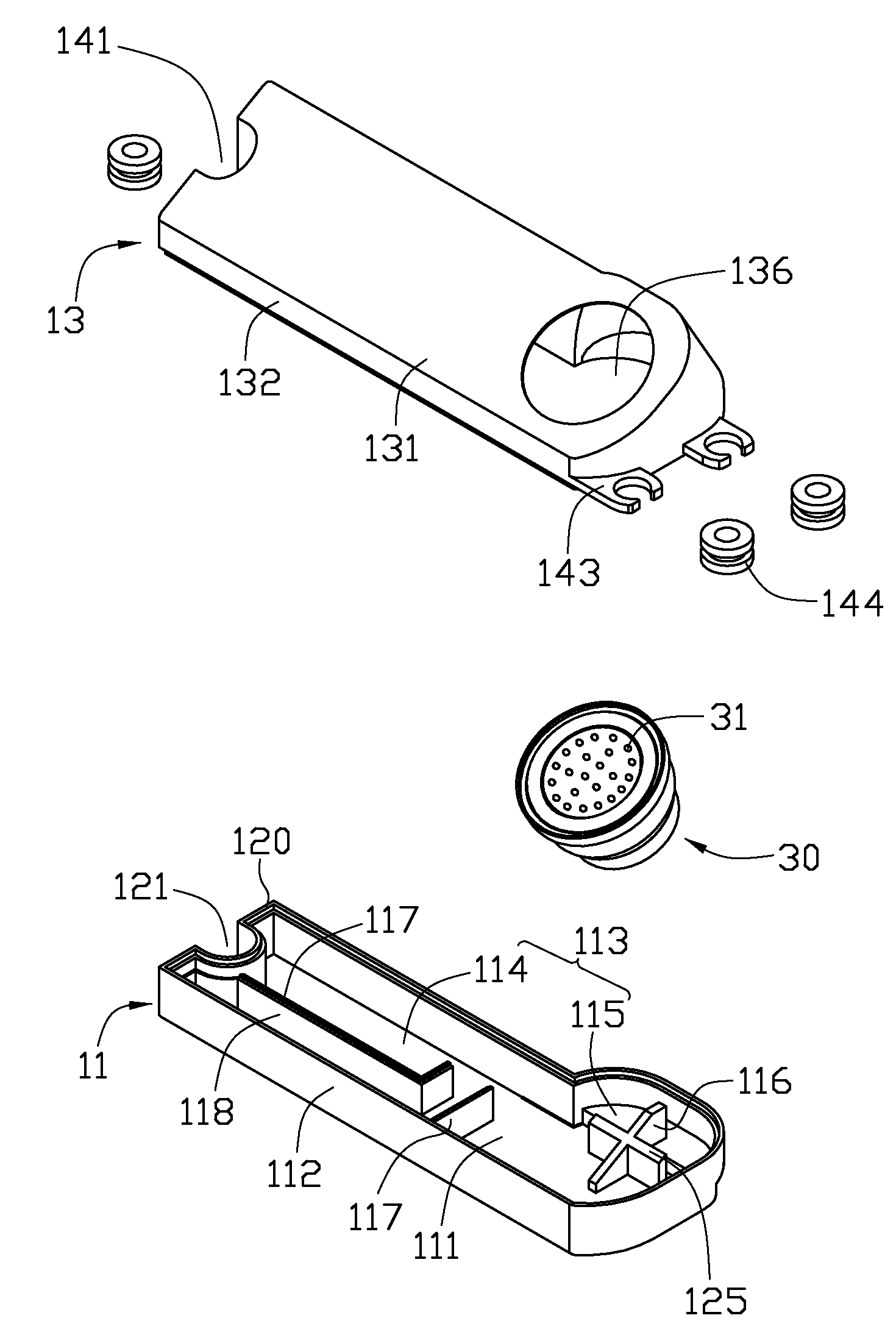
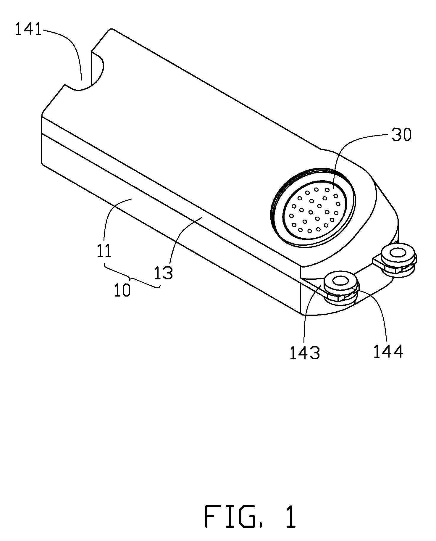
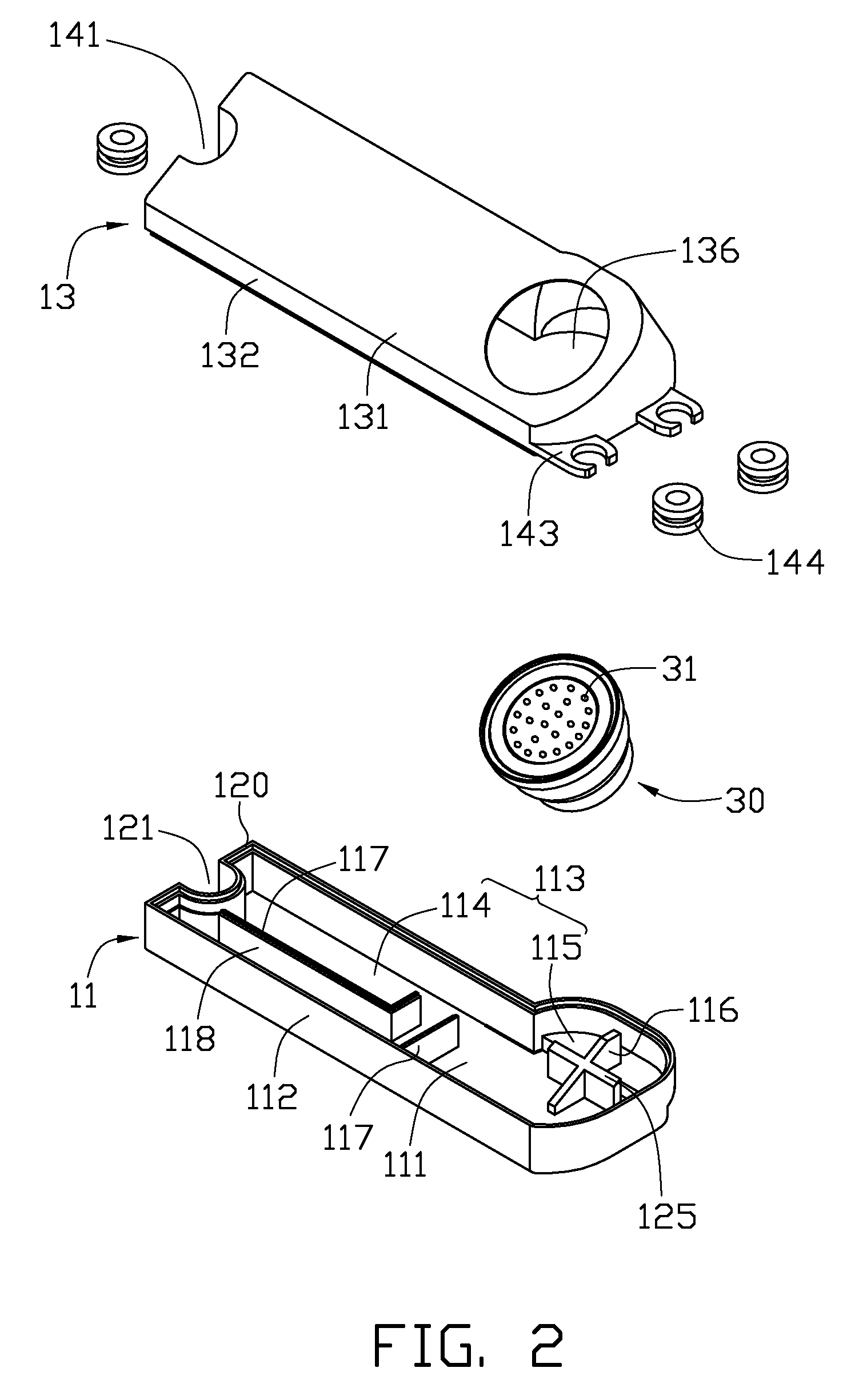
[0015]Referring to FIGS. 1 and 2, a sound box structure includes a shell 10 and a speaker 30 located therein.

[0016]The shell 10 is Mg—Al alloy, and includes a bottom cover 11 and a top cover 13 engaging the bottom cover 11. Both of the top and bottom covers 13, 11 are semi-enclosed.

[0017]The bottom cover 13 includes a bottom wall 111 and a sidewall 112 vertically and upwardly extending from an outer periphery of the bottom wall 111. The bottom wall 111 and sidewall 112 cooperatively form a chamber 113 therebetween. The chamber 113 includes a resonance chamber 114 and a receiving chamber 115 communicating with the resonance chamber 114. The receiving chamber 115 is substantially circular, and receives the speaker 30 therein. An X-shaped supporting portion 116 extends upwardly from the bottom wall 111 and within the receiving chamber 115. The supporting portion 116 has an inclined top surface 125, and an acute angle is defined between the top surface 125 and the bottom wall 111. Two c...


PUM


Abstract

A sound box structure includes a shell (10) and a speaker (30) received therein. The shell defines a resonance chamber (114) and a receiving chamber (115) communicating therewith. The speaker is received in the receiving chamber. The shell is Mg—Al alloy.

Description

BACKGROUND[0001]1. Technical Field[0002]The present invention generally relates to sound box structure, and particularly to a sound box structure used in an electronic device.[0003]2. Description of Related Art[0004]With the continuing development of technology, sound box structures have been widely used in electronic devices such as mobile phones, computers and other devices providing audio capabilities.[0005]A typical sound box structure generally includes a shell and a speaker located therein. The speaker converts electric energy to vibration for producing sound. In addition to housing the speaker, the shell plays an important role in the quality of the sound transmitted. Resonance chamber size promotes corresponding mass of air driven, with commensurate quality of low frequencies transmitted. Larger resonance chambers reduce resistance of the air therein, with low frequency effect improving accordingly.[0006]Currently, sound box shell structures are generally plastic. Due to low...

Claims


Application Information

Patent Timeline
IPC IPC(8): A47B81/06
CPCH04M1/035H04R2499/11H04R1/2888H04R1/2857
Inventor CHEN, HWANG-MIAWCHEN, HUI-CHENGCHIU, SHIH-CHIAPAN, CHENG-CHIA
Owner HON HAI PRECISION IND CO LTD
Why Eureka
Try Eureka