Jet type borehole cleaning tool

A cleaning tool and jet technology, which is applied in the direction of flushing wellbore, wellbore/well components, earth-moving drilling, etc., can solve the problems of increasing drilling time, increasing drilling operation cost, increasing friction, etc., and achieving chip carrying capacity Enhanced, simple structure, low cost effect

Active Publication Date: 2019-02-01
NORTHEAST GASOLINEEUM UNIV
View PDF8 Cites 1 Cited by
  • Summary
  • Abstract
  • Description
  • Claims
  • Application Information

AI Technical Summary

Problems solved by technology

[0004] The object of the present invention is to provide a jet-type wellbore cleaning tool, which is used to solve the problem of increased frictional resistance, increased drilling time, and increased drilling time due to the formation of cuttings beds during the drilling process. job cost problem

Method used


Image

  • Jet type borehole cleaning tool
  • Jet type borehole cleaning tool
  • Jet type borehole cleaning tool

Examples


Embodiment Construction

[0028] Below in conjunction with accompanying drawing, the present invention will be further described:

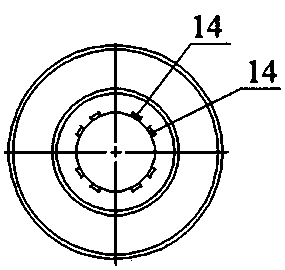
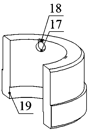
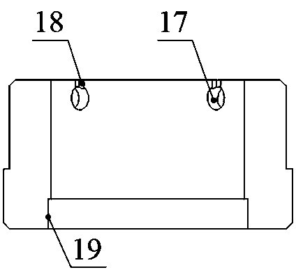
[0029] like figure 1 As shown, this jet type wellbore cleaning tool includes a casing joint 1, a valve block 3, a sliding block 4, a rubber switch 7, a rotating disk 6, and a lower joint 9; the lower joint 9 is fastened to the lower end of the shell joint 1 by threads, and the lower see link Figure 9 , the upper end of the shell joint 1 has a female buckle 16, the rotating disk 6 is arranged between the step of the shell joint 1 and the upper end surface of the lower joint 9, and the conversion bearing 2 is respectively installed between the two ends of the rotating plate 6 and the shell joint 1, and the upper valve block, The lower valve block is respectively fixed in the annular cavity between the rotating disc 6 and the shell joint 1, the upper valve block and the lower valve block are respectively connected to a conversion bearing 2, and the annular cavity between th...


PUM


Abstract

The invention relates to a jet type borehole cleaning tool. A rotating disc of the jet type borehole cleaning tool is arranged between a step of a shell joint and the upper end surface of a lower joint; an upper valve block and a lower valve block are correspondingly fixed in an annular cavity between the rotating disc and the shell joint; the annular cavity between the two valve blocks is a liquid storage cavity; rotating jet holes are uniformly formed in the rotating disc corresponding to the liquid storage cavity; the upper valve block and the lower valve block are correspondingly providedwith water inlet holes and rubber grooves in pairs, and the water inlet holes communicate with the liquid storage cavity, and the rubber grooves correspondingly communicate with the inner cavity of ashell through rubber holes; a switch rod of a rubber switch is provided with a liquid inlet groove, and water inlet springs are arranged between switch heads and the rubber grooves; and two sliding blocks are arranged on the inner wall of the shell joint, the sliding blocks block a group of rubber holes below the sliding blocks correspondingly when the sliding blocks slide downwards, and startingsprings are arranged between the protruding lower end surfaces of the sliding blocks and sliding grooves. According to the jet type borehole cleaning tool, the jet flow stops, the rotation stops, thejet flow is automatically closed, and thus interference is not brought to the normal drilling process.

Description

Technical field: [0001] The invention relates to a wellbore cleaning device in the field of petroleum engineering, in particular to a jet-type wellbore cleaning tool. Background technique: [0002] Wells with complex structures such as horizontal wells and extended-reach wells can maximize the drainage area of ​​reservoirs and improve oil and gas recovery, and are widely used in the development of offshore oil and gas fields, the stable production increase of old oil fields, and the development of low-permeability oil and gas fields. However, in horizontal wells and extended-reach wells, the accumulation of cuttings to form the cuttings bed is common. The existence of the cuttings bed will reduce the annular gap, which may easily cause the possibility of poor pump and stuck pipe. In the area where the drilling tool deviates seriously from the center of the wellbore, due to the formation and existence of the cuttings bed, the torque of the drilling tool increases, making it d...

Claims


Application Information

Patent Timeline
Patent Type & Authority Applications(China)
IPC IPC(8): E21B21/00
CPCE21B21/00
Inventor 李玮李兵吴红军李占东董航苏崭
Owner NORTHEAST GASOLINEEUM UNIV
Why Eureka
Try Eureka