Pneumatic tire

A technology for pneumatic tires, tires, applied in tire parts, tire tread/tread pattern, transportation and packaging, etc., can solve problems such as increased traction

Active Publication Date: 2019-02-12
TOYO TIRE & RUBBER CO LTD
View PDF11 Cites 4 Cited by
  • Summary
  • Abstract
  • Description
  • Claims
  • Application Information

AI Technical Summary

Problems solved by technology

Also, since the main grooves are inclined relative to the tire circumference, traction on snow is increased
[0003] However, in the pneumat...

Method used


Image

  • Pneumatic tire
  • Pneumatic tire

Examples


Embodiment Construction

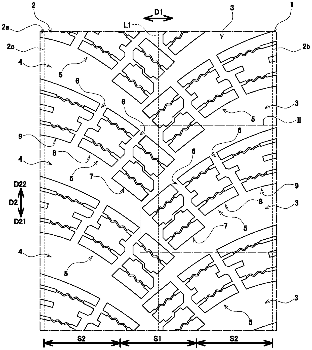
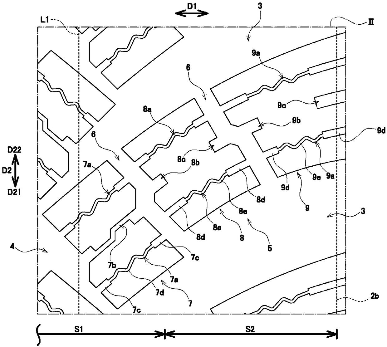
[0026] Below, refer to figure 1 as well as figure 2 , an embodiment of a pneumatic tire will be described. In addition, in each drawing, the dimensional ratios on the drawings do not necessarily match the actual dimensional ratios, and the dimensional ratios between the drawings do not necessarily match.

[0027] Such as figure 1 As shown, the pneumatic tire (hereinafter also simply referred to as "tire") 1 of this embodiment includes a pair of bead portions (not shown), and sidewall portions (not shown) extending radially outward from each bead portion. ) and a tread portion 2 connected to the outer end portions in the tire radial direction of a pair of sidewall portions and whose outer surface constitutes a tread 2a.

[0028] In addition, the tire 1 is attached to a rim (not shown), and the inside of the tire 1 is pressurized with air. The tire 1 of the present embodiment is a tire mainly used on snow and ice, for example, a tire used for a snow plow.

[0029] exist f...


PUM


Abstract

A pneumatic tire includes: a plurality of first main grooves, at least extending from a first ground end of a tire width direction to a tire equator, and extending toward a side of the circumferentialdirection of the tire with a second ground end side which trends to the width direction of the tire; a plurality of second main grooves, at least extending from the second ground end to the tire equator, and extending toward a side of the tire circumferential direction and trending to the first ground end side; and, a plurality of land portions which are marked out through connection of the second main groove and the two first main grooves. The land portion has a concave portion that extends toward one side of the tire circumferential direction with trending to the second ground end side on the center region of the tire width direction.

Description

technical field [0001] The present invention relates to a pneumatic tire including a plurality of main grooves extending from a ground contact end in the tire width direction to at least the tire equator. Background technique [0002] Conventionally, a pneumatic tire including a plurality of main grooves extending from a ground contact end in the tire width direction to a tire equator is known as a pneumatic tire (for example, Patent Document 1). Also, since the main grooves are inclined with respect to the tire circumferential direction, traction on snow is increased. [0003] However, in the pneumatic tire of Patent Document 1, it is a technical problem to improve dry performance, wet performance, and on-snow performance in a balanced manner. Therefore, it is necessary to further improve the on-snow performance and the on-ice performance of pneumatic tires mainly used on snow and ice, for example. [0004] prior art literature [0005] patent documents [0006] Patent ...

Claims


Application Information

Patent Timeline
IPC IPC(8): B60C11/03B60C11/12
CPCB60C11/0327B60C11/1236B60C11/1281B60C2011/0374B60C2011/0339B60C11/0302
Inventor 藤冈刚史
Owner TOYO TIRE & RUBBER CO LTD
Why Eureka
Try Eureka