Crane lifting device

A lifting device and driving-type technology, which is applied in the direction of the crane, hoist, and traveling mechanism of the trolley, can solve the problems of difficult lifting, unsmooth lifting, and inability to easily dodge obstacles, etc., and achieves simple structure and low occupation The effect of small space and improved flexibility

Active Publication Date: 2019-02-12
SICHUAN TAILONG CONSTR GRP CO LTD
View PDF10 Cites 0 Cited by
  • Summary
  • Abstract
  • Description
  • Claims
  • Application Information

AI Technical Summary

Problems solved by technology

[0003] In view of the above situation, the present invention provides a driving-type lifting device with simple structure, light use and strong flexibility, which solves the problem that existing

Method used


Image

  • Crane lifting device
  • Crane lifting device
  • Crane lifting device

Examples


Embodiment Construction

[0028] In order to facilitate the understanding of the present invention, the following will be described in conjunction with the accompanying drawings and embodiments.

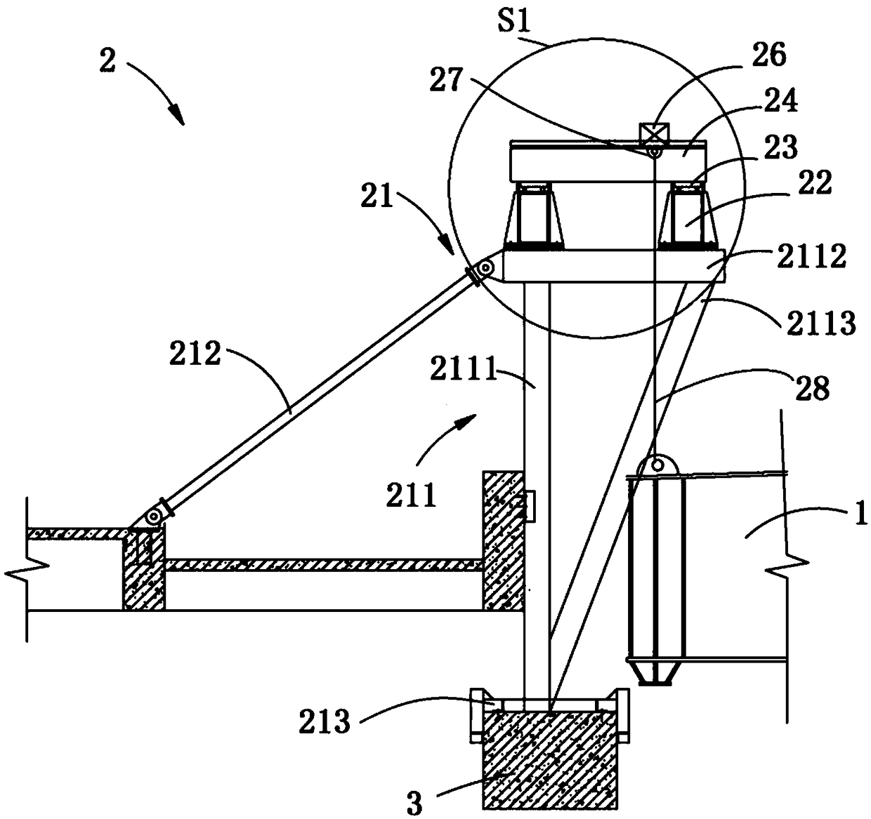
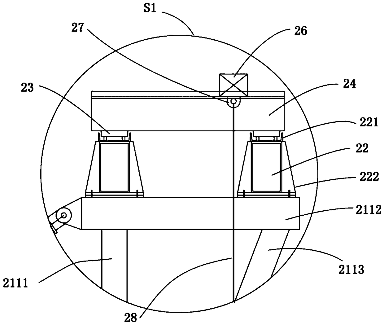
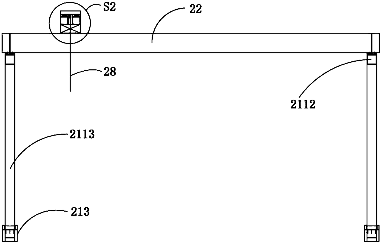
[0029] see Figure 1 to Figure 4 As shown, the present invention provides a driving-type lifting device for lifting a large-span hoisting object 1, the lifting device includes two sets of unit sections 2, and the two sets of unit sections 2 are respectively arranged on two structural beams 3 and extend along the length direction of each of the structural beams, the two structural beams 3 are arranged in parallel. In the embodiment of the present invention, the two structural beams 3 are respectively in the shape of a cuboid, and each group of the unit sections 2 includes a support seat 21, The walking longitudinal beam 22, the longitudinal traveling trolley 23, the traveling beam 24, the lateral traveling trolley 25, the connecting beam 26 and the electric hoist (not shown) arranged on the support base 21, th...


PUM


Abstract

The invention provides a crane lifting device. The crane lifting device comprises two sets of unit sections arranged on two structural beams; each set of unit sections comprises a support base, and awalking longitudinal beam, a longitudinal walking car, a walking cross beam, a transverse walking car, a connecting cross beam and an electric block arranged on the support base; the transverse walking car walks along with the longitudinal walking car to adjust the longitudinal displacement; the transverse walking car moves on the walking cross beam to adjust the transverse displacement; and the electric block is arranged on the connecting cross beam, and moves along with the transverse walking car to adjust the transverse displacement and the longitudinal displacement. The crane lifting device is simple in structure and convenient to use, has no need to use crane equipment with larger size, is less in occupied space, meanwhile, is not limited by the distance between building structures, and is suitable for lifting structures with large span and high weight between the building structures.

Description

technical field [0001] The invention relates to the technical field of building construction, in particular to a driving type lifting device. Background technique [0002] Some space structures with large spans, heavy weights and located in the center of the building have limited surrounding sites and are difficult to lift. Traditional construction methods include overall lifting, high-altitude scattered construction, and cumulative slippage, all of which have higher requirements on the site environment. , such as the overall lifting, requires a large lifting site and no obstacles around; high-altitude bulk consolidation requires full coverage of vertical transportation equipment, and the construction period is long; the cumulative slippage construction period is long, etc. Contents of the invention [0003] In view of the above situation, the present invention provides a driving-type lifting device with simple structure, light use and strong flexibility, which solves the ...

Claims


Application Information

Patent Timeline
IPC IPC(8): B66C11/00B66C7/00B66C9/00B66C19/00
CPCB66C7/00B66C9/00B66C11/00B66C19/00
Inventor 邱峰王显博张磊吕永进王立红王军杰周婷
Owner SICHUAN TAILONG CONSTR GRP CO LTD
Why Eureka
Try Eureka