

Anti-shock electronic control lock
An electronically controlled lock and lock housing technology, applied in the field of electronic locks, can solve the problems of low security, complex structure, and the lock is easy to be opened, etc., and achieves the effects of reducing costs, changing the driving mode, and high security.
- Summary
- Abstract
- Description
- Claims
- Application Information
AI Technical Summary
Problems solved by technology
Method used
Image

Examples
Embodiment Construction
[0018] In order to make the technical means, creative features, objectives and effects achieved by the present invention easy to understand, the present invention will be further elaborated below.
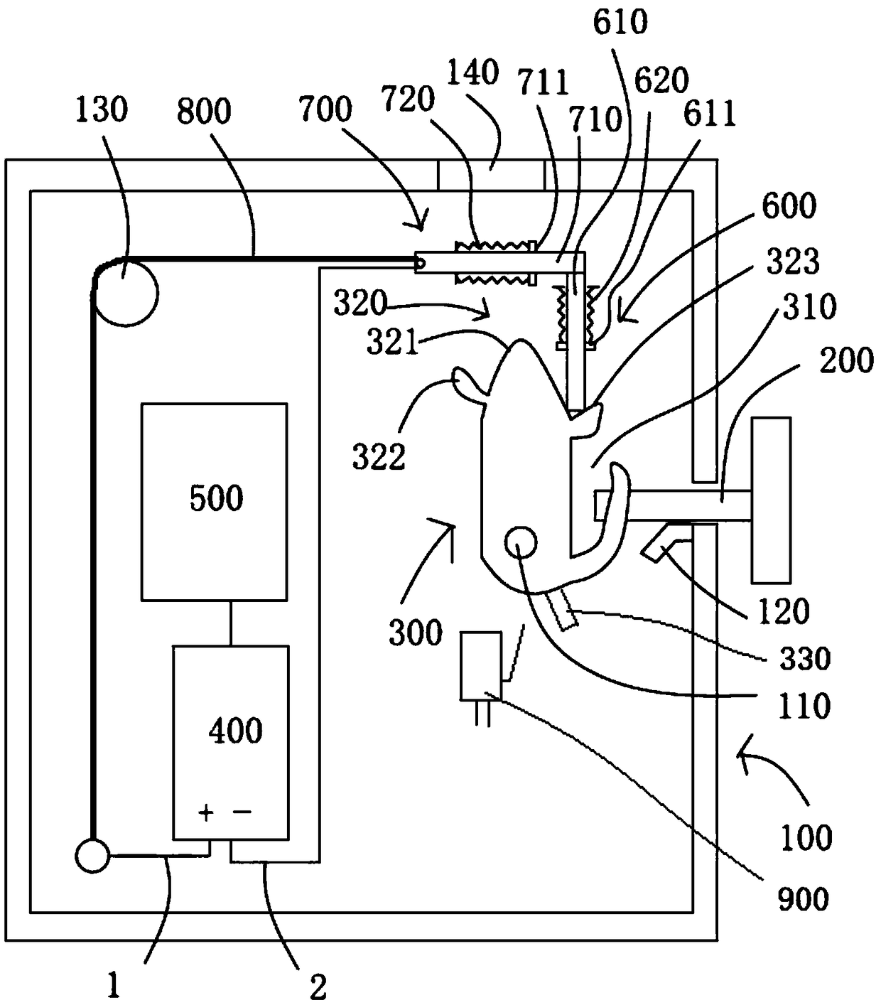
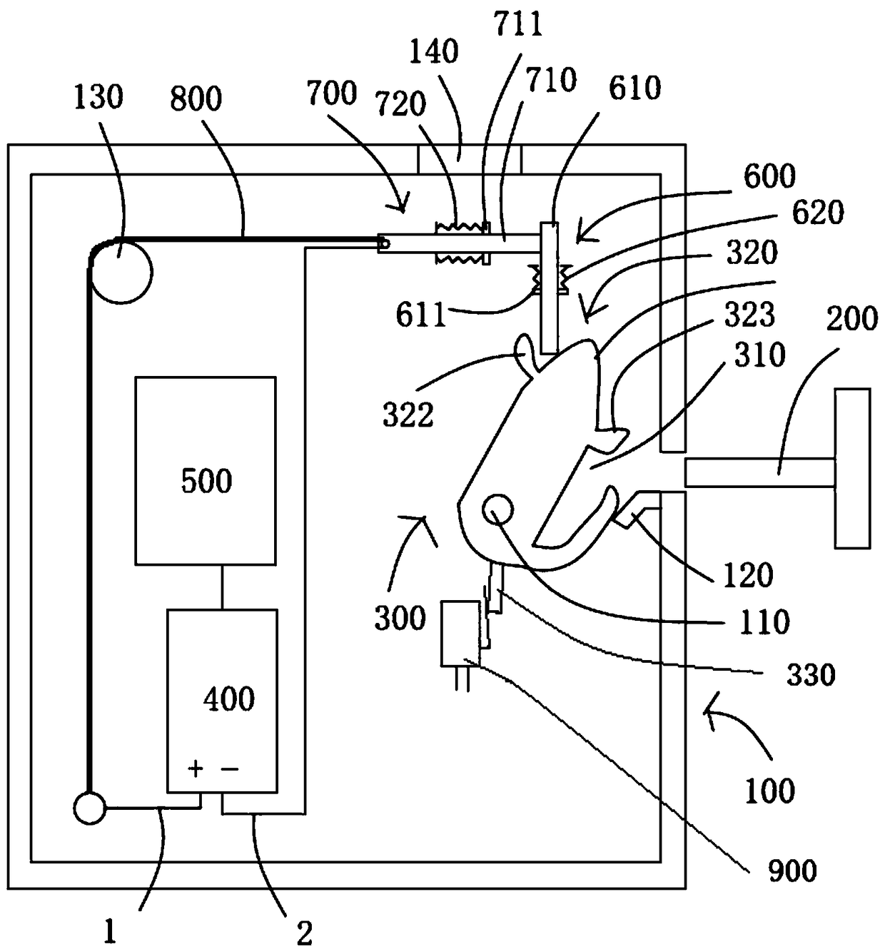
[0019] see figure 1 and figure 2 The anti-vibration electric control lock shown includes a lock case 100 corresponding to the lock hook 200 of the door body and a hook lever 300 rotatably arranged in the lock case 100 by a reset torsion spring 110 . The hook lever 300 has a locking groove 310 corresponding to the locking hook 200 and a hook lever stop surface 320 , and a power module 400 and a circuit board 500 are arranged in the lock housing.
[0020] The hook lever stop surface 320 has a transition arc surface 321 and an unlock stop portion 322 and a lock stop portion 323 respectively located at two ends of the transition arc surface 321. In this embodiment, the unlock stop portion 322 and the lock stop portion The moving parts 323 are respectively stop edges with radians. T...
PUM
 Abstract
Description
Claims
Application Information