
Roadside parking management system based on camera matrix

A management system and camera technology, applied in the computer field, can solve problems such as limited field of view, video pile occlusion, and low timing accuracy, and achieve the effect of expanding the detection angle, improving accuracy, and improving accuracy

Inactive Publication Date: 2019-02-12
INTELLIGENT INTER CONNECTION TECH CO LTD
View PDF7 Cites 10 Cited by
  • Summary
  • Abstract
  • Description
  • Claims
  • Application Information

AI Technical Summary

Problems solved by technology

[0003] 1) Manual management method: In several parking lots, the toll collectors manage and charge for parking on the roadside. Although this method is simple to implement, there are many problems, such as the limited movement speed of personnel will lead to restricted management scope 1. Errors caused by human factors lead to missed detection of entering vehicles, confusion of charges due to wrong judgments of personnel, disputes caused by insufficient evidence collection, and with the continuous increase of personnel costs, a large amount of additional expenses will be caused;
[0004] 2) Geomagnetic management method: Geomagnetic equipment is buried on the ground of the road berth, and personnel can be notified to charge when the vehicle enters. This method of management is relatively simple, but it also requires management personnel to cooperate with charging, and there is insufficient evidence collection and low timing accuracy. In addition, due to the huge amount of construction, large-scale reconstruction of urban roads is required, which will also affect the traffic of urban roads during the construction period;
[0005] 3) Video pile management method: video piles are erected near each berth on the road. Although this method solves the problem of obtaining evidence for vehicles entering and leaving the berth, the height of the video pile is generally similar to the height of the vehicle, and the field of vision for video shooting is limited. For vehicles parked irregularly in the berth, it is easy to cause the angle between the video pile and the license plate of the irregularly parked vehicle to be too large, so that the license plate cannot be photographed, or the video pile is blocked by the vehicle in the parking lot, and the license plate cannot be photographed; at the same time, the video pile is placed It needs to be placed according to the berth, the construction volume is huge, and the cost is high; in addition, due to the low height of the video pile, there is a risk of artificially blocking or destroying the video pile;
[0006] 4) Shooting camera management method: set up a camera pole on one side of the road, use a shooting camera to track and shoot, and use the ball camera to capture and collect evidence; this method can automatically identify vehicles entering and exiting berths, and realize automatic evidence collection and billing, and The construction cost is very low, but there are still many problems. For example, when the vehicle enters and exits the berth, the dome camera may not respond in time, so that it cannot adjust the pan / tilt in time to focus and capture the evidence of the vehicle entering and leaving the field; When the vehicle at the end berth is recognized, the angle of view of the camera will become very small, and the recognition accuracy will drop rapidly. At the same time, the dome camera will also be unable to accurately capture the movement of the vehicle entering and leaving the field due to the longer focusing time when capturing the far end berth. occur

Method used


Image

  • Roadside parking management system based on camera matrix
  • Roadside parking management system based on camera matrix
  • Roadside parking management system based on camera matrix

Examples


Embodiment Construction

[0021] The following will clearly and completely describe the technical solutions in the embodiments of the present invention with reference to the accompanying drawings in the embodiments of the present invention. Obviously, the described embodiments are only some, not all, embodiments of the present invention. Based on the embodiments of the present invention, all other embodiments obtained by persons of ordinary skill in the art without making creative efforts belong to the protection scope of the present invention.

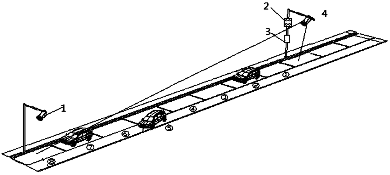
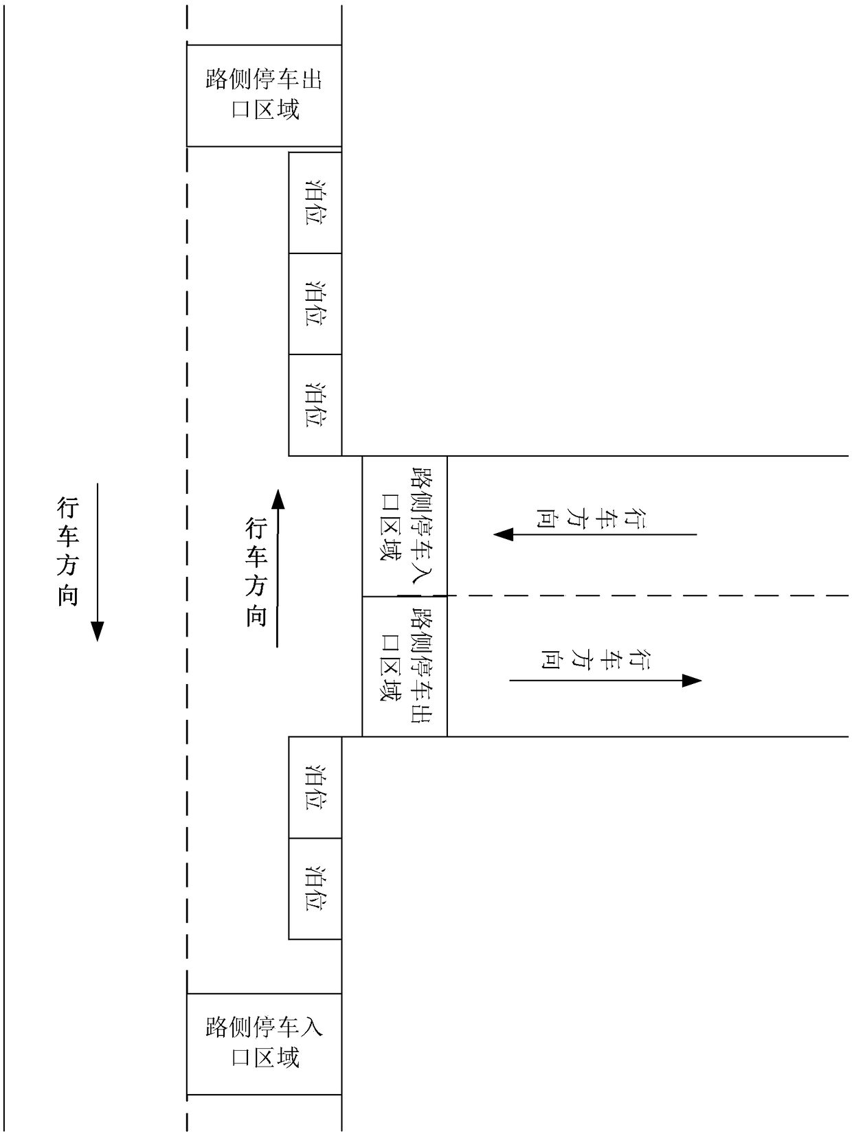
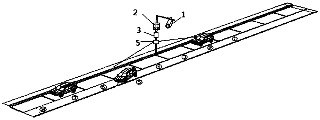
[0022] Such as figure 1 As shown, it is a camera matrix-based on-street parking management system in an embodiment of the present invention, including: a roadside parking entrance and exit area camera, a first camera matrix, a main controller, and at least one installation pole or installation position;

[0023] The at least one installation pole or installation position is arranged in the roadside parking area;

[0024] The roadside parking entrance and exit...


PUM


Abstract

The embodiment of the invention provides a roadside parking management system based on a camera matrix. The roadside parking management system based on the camera matrix comprises a roadside parking access region camera, a first camera matrix, a main controller and at least one installation rod or installation position; the roadside parking access region camera is used for acquiring regional images of a roadside parking entrance region and a roadside parking exit region; the first camera matrix is used for acquiring a vehicle information image of a berth in the first predetermined acquisitionrange from the installation rod or the installation position; and the main controller is used for determining the occupation information of each berth in the roadside parking region according to the acquired regional image of the roadside parking entrance and / or exit region and the vehicle information image of the berth in the first predetermined acquisition range, so that roadside parking management is realized. By means of the embodiment, unattended management on roadside parking is realized; and a vehicle parking event can be judged in time more accurately.

Description

technical field [0001] The invention relates to the technical field of computers, in particular to a camera matrix-based roadside parking management system. Background technique [0002] Urban roadside parking, also known as roadside parking or on-street parking, has always been a difficult problem in urban management. Urban roadside parking is generally an open parking lot, which is not restricted by barriers such as barriers, so it is impossible to enter and exit uniformly. On the one hand, due to the straight-line parking on the roadside, it is easy to happen that the front car is blocked by the rear car and the license plate number cannot be seen clearly; on the other hand, usually a roadside parking lot is often occupied by several vehicles. The entrance and exit are divided into several small roadside parking, but there are vehicles entering and exiting in each small intersection, which affects the judgment of the actual parking vehicle entering and exiting the field. ...

Claims


Application Information

Patent Timeline
IPC IPC(8): H04N7/18G08G1/017G08G1/14H04N5/235G07B15/02G06K9/32
CPCH04N7/181G07B15/02G08G1/0175G08G1/14G06V10/25G06V20/625H04N23/74
Inventor 闫军侯林赵世琦
Owner INTELLIGENT INTER CONNECTION TECH CO LTD
Learn More