Obstacle detection method, obstacle detection module and self-moving device

An obstacle detection and obstacle technology, applied in the field of obstacle detection, can solve problems such as the inability to detect obstacles more comprehensively, and achieve the effect of accurately constructing maps, avoiding obstacles, and expanding the perspective of obstacle detection.

Pending Publication Date: 2021-09-03
SHENZHEN SILVER STAR INTELLIGENT TECH CO LTD
View PDF6 Cites 0 Cited by
  • Summary
  • Abstract
  • Description
  • Claims
  • Application Information

AI Technical Summary

Problems solved by technology

[0004] An object of the embodiments of the present invention is to provide an obstacle detection method, an obstacle detection module and a self-moving device, which are used to solve the problem that obstacles cannot be detected more comprehensively at present

Method used


Image

  • Obstacle detection method, obstacle detection module and self-moving device
  • Obstacle detection method, obstacle detection module and self-moving device
  • Obstacle detection method, obstacle detection module and self-moving device

Examples


Embodiment 1

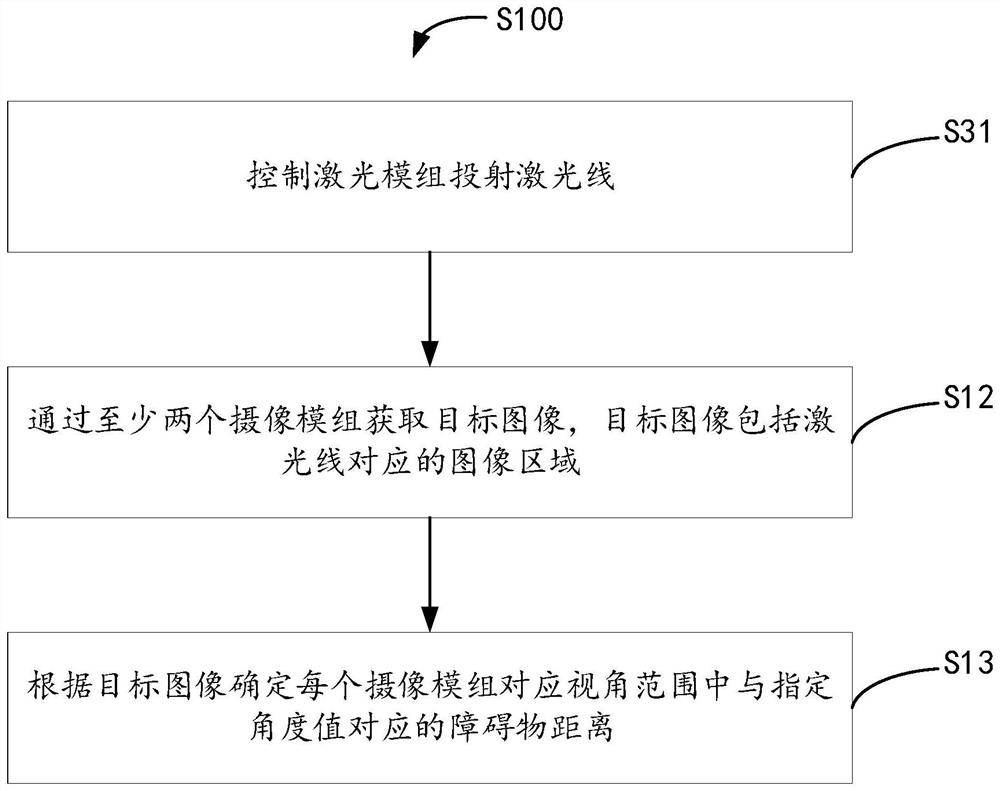
[0050] An embodiment of the present invention provides an obstacle detection method. The obstacle detection method is applied to an obstacle detection module. The obstacle detection module includes a laser module and at least two camera modules. Please refer to figure 1 , the obstacle detection method S100 includes:

[0051] S11. Control the laser module to project the laser line.

[0052] As an example and not limitation, the laser module can project laser lines in the target space, where the target space includes the space where the obstacle detection module is currently located, for example, the target space is an indoor space, and the indoor space includes Various rooms, such as bedroom, kitchen, living room.

[0053] S12. Obtain a target image through at least two camera modules, where the target image includes an image area corresponding to the laser line.

[0054] Wherein, the image area corresponding to the laser line refers to: the image area formed by the laser line ...

Embodiment 2

[0123] An embodiment of the present invention provides an obstacle detection module.

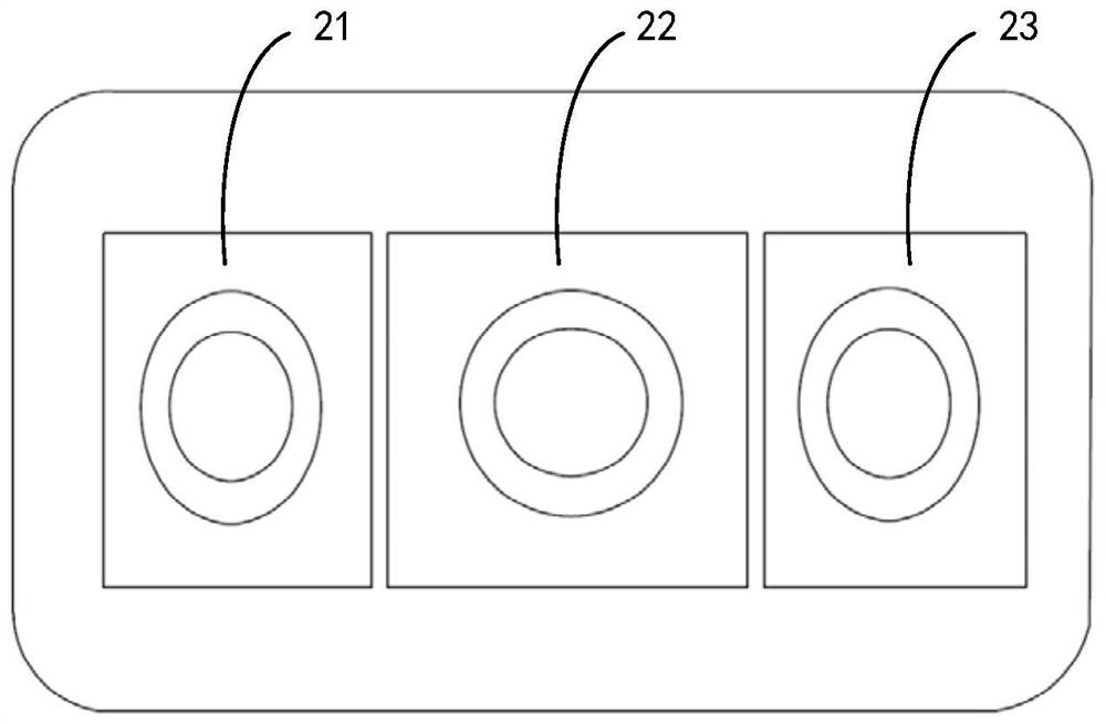
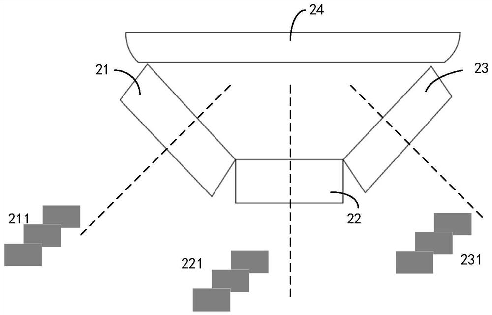
[0124] By way of example and not limitation, see Figure 7 , the obstacle detection module 700 includes a laser module 71 , at least two camera modules 72 and a control unit 73 .

[0125] The laser module 71 is used to project the laser line, and at least two camera modules 72 are used to obtain the target image. The target image includes the image area corresponding to the laser line. The connection is used to implement the obstacle detection method described in the above-mentioned embodiments.

[0126] Since multiple camera modules can be installed, the obstacle detection module 700 can expand the obstacle detection angle of view, which is beneficial for the obstacle detection module 700 to detect a space with a larger angle of view, so that obstacles can be detected in all directions, thereby reducing the distance between The collision probability of the obstacle.

[0127] In some embo...

Embodiment 3

[0130] An embodiment of the present invention provides an autonomous mobile device, which includes the obstacle detection module described in the foregoing embodiments.

[0131] As an example and not limitation, the self-moving device provided in the embodiment of the present invention may be a robot, and the robot may be specifically a cleaning robot, which may implement at least one of the following functions: sweeping, mopping, scrubbing, and vacuuming.

[0132] Since multiple camera modules can be installed, the self-mobile device can expand the obstacle detection angle of view, which is beneficial for the self-mobile device to detect a space with a larger viewing angle range, so that obstacles can be detected more comprehensively, thereby reducing the probability of collision with obstacles.

[0133] The device or device embodiments described above are only illustrative, and the unit modules described as separate components may or may not be physically separated, and the c...


PUM


Abstract

The invention relates to the technical field of obstacle detection, in particular to an obstacle detection method, an obstacle detection module and self-moving equipment. The obstacle detection method is applied to an obstacle detection module, the obstacle detection module comprises a laser module and at least two camera modules, and the method comprises the steps that the laser module is controlled to project laser rays, a target image is acquired through the at least two camera modules, and the target image comprises an image area corresponding to the laser rays; and determining an obstacle distance corresponding to the specified angle value in the visual angle range corresponding to each camera module according to the target image. As a plurality of camera modules can be installed, the obstacle detection visual angle of the obstacle detection module can be increased, and the obstacle detection module can detect a space with a larger visual angle range, so that the obstacle can be detected more comprehensively.

Description

technical field [0001] The invention relates to the technical field of obstacle detection, in particular to an obstacle detection method, an obstacle detection module and self-moving equipment. Background technique [0002] With the development of robot technology, robots gradually enter ordinary families, gradually liberating people from heavy and trivial housework, thus providing great convenience for people. [0003] Existing robots are generally equipped with cameras to detect obstacles. However, the shooting angles of current cameras are relatively small, which is not conducive to more comprehensive detection of obstacles. Contents of the invention [0004] An object of the embodiments of the present invention is to provide an obstacle detection method, an obstacle detection module and a self-moving device, which are used to solve the current problem that obstacles cannot be detected comprehensively. [0005] In a first aspect, an embodiment of the present invention ...

Claims


Application Information

Patent Timeline
Patent Type & Authority Applications(China)
IPC IPC(8): G06K9/00G06T7/70
CPCG06T7/70G06T2207/30244
Inventor 袁健
Owner SHENZHEN SILVER STAR INTELLIGENT TECH CO LTD
Why Eureka
Try Eureka