Smart home with real-time wireless temperature and humidity control function

A smart home and wireless control technology, applied in the direction of simultaneous control of multiple variables, non-electric variable control, control/regulation systems, etc., can solve the problems of not being able to adjust temperature and humidity in time, achieve simple structure, and avoid the trouble of wiring , Realize the effect of real-time adjustment

Inactive Publication Date: 2019-02-15
广州优里贸易有限公司
View PDF0 Cites 3 Cited by
  • Summary
  • Abstract
  • Description
  • Claims
  • Application Information

AI Technical Summary

Problems solved by technology

[0002] With the improvement of people's requirements for home comfort and health, the concept of smart home is gradually proposed and accepted. Smart home generally uses advanced computer network communication technology, integrated wiring technology and ergonomic principles to integrate individual needs, and will integrate with home life. The relevant subsystems are organically combined to achieve a new home life experience through comprehensive intelligent control and management. At present, cooling and heating in family life is a major event, which has a major impact on people's living comfort. However, cooling and heating needs Real-time adjustments are made according to the feelings of the human body. Ordinary collective heating and air-conditioning refrigeration have great limitations, and cannot adjust temperature and humidity in time.

Method used


Image

  • Smart home with real-time wireless temperature and humidity control function
  • Smart home with real-time wireless temperature and humidity control function
  • Smart home with real-time wireless temperature and humidity control function

Examples


Embodiment Construction

[0013] The present invention is further described in conjunction with the following examples.

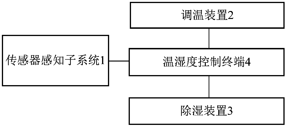
[0014] figure 1 It is a schematic block diagram of a smart home structure for real-time wireless temperature and humidity control according to an embodiment of the present invention. see figure 1 A smart home with real-time wireless temperature and humidity control provided in this embodiment includes a sensor sensing subsystem 1, a temperature adjustment device 2, a dehumidification device 3, and a temperature and humidity control terminal 4, wherein the sensor sensing subsystem 1, the temperature adjustment device 2, The dehumidifiers 3 are all connected to the temperature and humidity control terminal 4 .

[0015] Among them, the sensor perception subsystem 1 is configured to monitor the indoor temperature and humidity in real time, collect indoor temperature and humidity data and send them to the temperature and humidity control terminal 4 .

[0016] The sensor sensing subsys...


PUM


Abstract

The invention provides a smart home with a real-time wireless temperature and humidity control function, which comprises a sensor sensing subsystem, a temperature adjustment device, a dehumidificationdevice and a temperature and humidity control terminal. The sensor sensing subsystem, the temperature adjustment device and the dehumidification device are connected with the temperature and humiditycontrol terminal. The sensor sensing subsystem is configured to monitor the indoor temperature and humidity in real time, collect indoor temperature and humidity data and send the indoor temperatureand humidity data to the temperature and humidity control terminal. The temperature and humidity control terminal is configured to analyze and process the received indoor temperature and humidity data, generate corresponding control instructions and control the operation of the temperature adjustment device and the dehumidification device according to the control instructions. The sensor sensing subsystem includes a single sink node and multiple sensor nodes deployed in a monitoring area. The sensor nodes collect the indoor temperature and humidity data and send the indoor temperature and humidity data to the sink node, and the sink node sends the indoor temperature and humidity data to the temperature and humidity control terminal.

Description

technical field [0001] The invention relates to the field of smart home, in particular to a smart home with real-time wireless temperature and humidity control. Background technique [0002] With the improvement of people's requirements for home comfort and health, the concept of smart home is gradually proposed and accepted. Smart home generally uses advanced computer network communication technology, integrated wiring technology and ergonomic principles to integrate individual needs, and will integrate with home life. The relevant subsystems are organically combined to achieve a new home life experience through comprehensive intelligent control and management. At present, cooling and heating in family life is a major event, which has a major impact on people's living comfort. However, cooling and heating needs Real-time adjustments are made according to the feelings of the human body. Ordinary collective heating and air-conditioning refrigeration have great limitations and...

Claims


Application Information

Patent Timeline
Patent Type & Authority Applications(China)
IPC IPC(8): G05D27/02G08C17/02
CPCG05D27/02G08C17/02
Inventor 不公告发明人
Owner 广州优里贸易有限公司
Why Eureka
Try Eureka