
Ventilation trigger device and method for anesthesia machine

A technology of triggering device and anesthesia machine, applied in the field of anesthesia machine, can solve the problems of difficult adjustment of patients under local anesthesia, single ventilation mode of anesthesia machine, and inability to change simultaneous modes, etc., and achieves the effect of safe and convenient use, scientific and reasonable structure

Active Publication Date: 2021-03-26
牡丹江医学院附属红旗医院
View PDF18 Cites 0 Cited by
  • Summary
  • Abstract
  • Description
  • Claims
  • Application Information

AI Technical Summary

Problems solved by technology

[0003] The present invention provides a ventilation trigger device and method for an anesthesia machine, which can effectively solve the problem that the ventilation mode of the common anesthesia machine proposed in the above background technology is single, and the simultaneous mode cannot be changed according to the specific conditions of the patient under local anesthesia, and the common The ventilation trigger device of the anesthesia machine is integrated with the anesthesia machine. When the doctor or nursing staff is away, it is difficult for patients under local anesthesia to adjust themselves.

Method used


Image

  • Ventilation trigger device and method for anesthesia machine
  • Ventilation trigger device and method for anesthesia machine
  • Ventilation trigger device and method for anesthesia machine

Examples


Embodiment 1

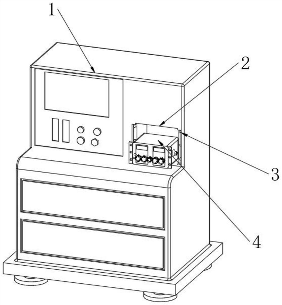
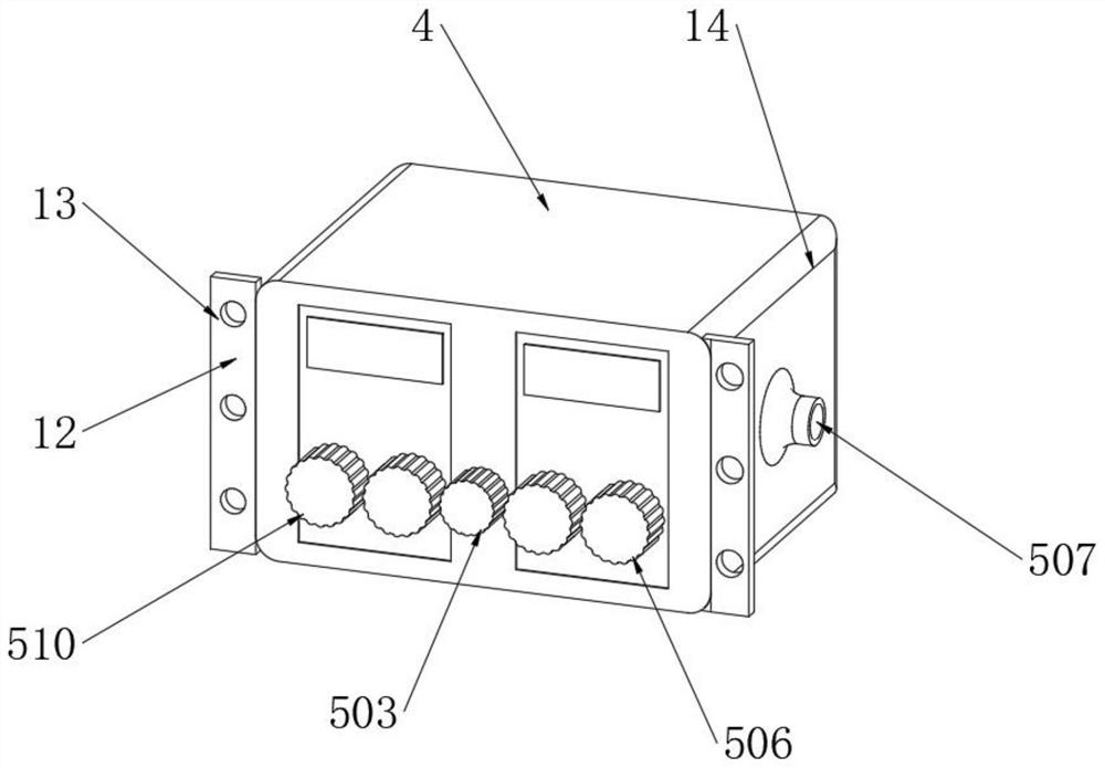
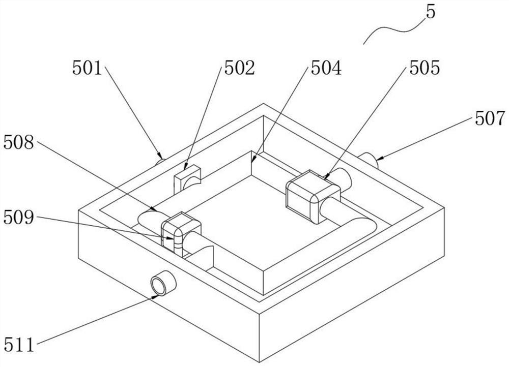
[0039] Embodiment 1: as Figure 1-7 As shown, the present invention provides a technical solution, a ventilation trigger device for an anesthesia machine, including an anesthesia machine 1, a trigger box 4 is installed inside one side of the anesthesia machine 1, in order to facilitate storage of the trigger box 4, the anesthesia machine 1- The side is provided with an inner groove 2, and both sides of the inner groove 2 are provided with connecting side grooves 3. In order to facilitate the fixing of the trigger box 4, fixed edge strips 12 are installed at both ends of one side of the trigger box 4, and the interior of the fixed edge strips 12 is uniform. There are fixed threaded holes 13, and the four corners of the trigger box 4 are sleeved with buffer strips 14 to reduce the friction loss generated when the trigger box 4 moves. The trigger box 4 is equipped with a trigger conversion assembly 5, and the trigger conversion assembly 5 includes an intake pipe 501 , main valve ...


PUM


Abstract

The invention discloses a ventilation triggering apparatus and method for an anaesthesia machine. The ventilation triggering apparatus comprises an anaesthesia machine, wherein a triggering changeoverassembly is installed inside the anaesthesia machine, and the bottom end of the triggering changeover assembly is provided with a supporting assembly. The ventilation triggering apparatus is scientific and reasonable in structure, and safe and convenient in use; by arranging the triggering changeover assembly, by virtue of the effect of a volume fixing branch pipe, a volume fixing valve and a volume fixing valve adjusting knob, convenience can be brought to a locally narcotized patient, the flow rate of the gas in the pipeline can be adjusted according to the requirement of the locally narcotized patient, so that the airflow with certain constant flow rate can be provided for the locally narcotized patient; and by virtue of the effect of an air inlet main pipe, a main valve, a main valveknob, a constant pressure branch pipe, a constant pressure valve, a constant pressure valve adjusting knob and a pressure supply pipe, the ventilation triggering apparatus can be conveniently switchedto a constant pressure mode; and the pressure of the gas in the pipeline can be adjusted according to the requirement of the locally narcotized patient, and the airflow with the given pressure can beprovided for the locally narcotized patient, so that the ventilation triggering apparatus can be triggered to change the ventilation mode according to the specific situation.

Description

technical field [0001] The invention relates to the technical field of anesthesia machines, in particular to a ventilation trigger device and method for anesthesia machines. Background technique [0002] The anesthesia machine sends the anesthetic into the alveoli of the patient through a mechanical circuit, forming a partial pressure of the anesthetic gas, which diffuses into the blood, and directly inhibits the central nervous system, thereby producing the effect of general anesthesia. At the same time, the anesthesia machine can also provide patients with It provides multiple functions such as assisted breathing. The ventilation mode of ordinary anesthesia machines is single, and the simultaneous mode cannot be changed according to the specific conditions of patients under local anesthesia. Moreover, the ventilation trigger device of ordinary anesthesia machines is integrated with the anesthesia machine. When a doctor or nurse It is difficult for patients under local anes...

Claims


Application Information

Patent Timeline
Patent Type & Authority Patents(China)
IPC IPC(8): A61M16/01
CPCA61M16/01A61M2202/0241A61M2205/33A61M16/0003A61M2202/0007
Inventor 刘岩张艳丽王洋陈猛芦相玉吴晓炀
Owner 牡丹江医学院附属红旗医院
Learn More