Control valve with adjusting function

A technology for controlling valves and functions, which is applied in the direction of functional valve types, sliding valves, valve details, etc., and can solve problems such as device blockage, material spraying, and impact on blanking, and achieve the effects of improving practicability, avoiding waste, and improving quality

Inactive Publication Date: 2018-09-28
鄢碧珠
View PDF0 Cites 0 Cited by
  • Summary
  • Abstract
  • Description
  • Claims
  • Application Information

AI Technical Summary

Problems solved by technology

[0002] Valves are the control components in the fluid delivery system, with the functions of cut-off, regulation, flow diversion, reverse flow prevention, pressure stabilization, flow diversion or overflow pressure relief, etc. Valves used in fluid control systems range from the simplest cut-off valve to extremely complex The various valves used in the automatic control system have a wide variety of varieties and specifications. The valves can be used to control the flow of various types of fluids such as air, water, steam, various corrosive media, mud, oil, liquid metal and radioactive media. According to the material, valves are also divided into cast iron valves, cast steel valves, stainless steel valves (201, 304, 316, etc.), chrome molybdenum steel valves, chrome molybdenum vanadium steel valves, duplex steel valves, plastic valves, non-standard custom valves, etc. Material, while the traditional blanking valve only has the function of switch and diversion during use, and cannot filter the raw materials during use, which will easily lead to blockage of the device and affect the progress of blanking, and in the process of blanking, lack of The pressure stabilizing component cannot stabilize the pressure of the discharge port, which will easily cause material spraying and waste of materials. At the same time, it cannot control the speed of feeding, and cannot accurately adjust the feeding rate according to the demand of raw materials. The functionality is low. Inconvenient to use

Method used


Image

  • Control valve with adjusting function
  • Control valve with adjusting function
  • Control valve with adjusting function

Examples


Embodiment Construction

[0015] The following will clearly and completely describe the technical solutions in the embodiments of the present invention with reference to the accompanying drawings in the embodiments of the present invention. Obviously, the described embodiments are only some, not all, embodiments of the present invention. Based on the embodiments of the present invention, all other embodiments obtained by persons of ordinary skill in the art without making creative efforts belong to the protection scope of the present invention.

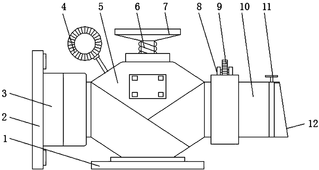
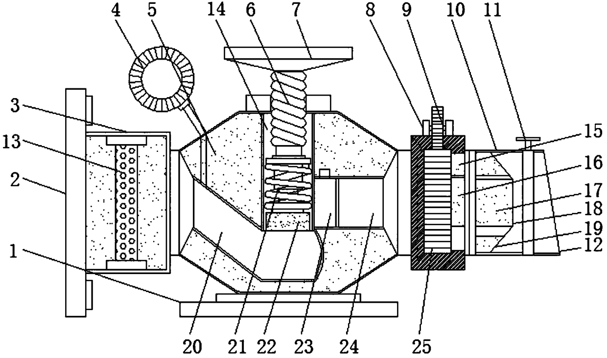
[0016] see Figure 1-3 , the embodiment provided by the present invention: a control valve with regulating function, including a base 1, a pressure regulating chamber 5 is arranged at the middle position of the top of the base 1, and a feed pipe 20 is arranged on one side inside the pressure regulating chamber 5 , a pressure regulating tube 14 is provided at the middle position inside the pressure regulating chamber 5, and the pressure regulating pipe 14 commu...


PUM


Abstract

The invention discloses a control valve with an adjusting function. The control valve comprises a base, a pressure adjusting cabin is arranged at the middle position of the top of the base, a feedingpipe is arranged on one side in the pressure adjusting cabin, a pressure adjusting pipe is arranged at the middle position in the pressure adjusting cabin, and the pressure adjusting pipe communicateswith the feeding pipe. A threaded rod is arranged in the pressure adjusting pipe, the threaded rod extends to the outer side of the pressure adjusting cabin, a rotating wheel is arranged at the top of the threaded rod, and an extrusion structure is arranged at the bottom of the threaded rod. A filtering cabin is installed, raw materials can be filtered by a filter net inside the filter cabin to remove impurities in the raw materials, the quality of the raw materials after feeding is improved, the use of the raw materials is facilitated, and the pressure adjusting cabin is arranged in the control valve to adjust the pressure during discharging to prevent the raw materials from spraying due to excess pressure, so that the discharging is more stable, and the waste of the raw materials is avoided.

Description

technical field [0001] The invention relates to the technical field of valves, in particular to a control valve with regulating function. Background technique [0002] Valves are the control components in the fluid delivery system. They have the functions of cut-off, adjustment, flow diversion, reverse flow prevention, pressure stabilization, flow diversion or overflow pressure relief. Valves used in fluid control systems range from the simplest cut-off valve to extremely complex The various valves used in the automatic control system have a wide variety of varieties and specifications. The valves can be used to control the flow of various types of fluids such as air, water, steam, various corrosive media, mud, oil, liquid metal and radioactive media. According to the material, valves are also divided into cast iron valves, cast steel valves, stainless steel valves (201, 304, 316, etc.), chrome molybdenum steel valves, chrome molybdenum vanadium steel valves, duplex steel va...

Claims


Application Information

Patent Timeline
IPC IPC(8): F16K17/20F16K3/08F16K3/314F16K3/30F16K3/34F16K37/00F16K27/00B01D35/02
CPCF16K17/20B01D35/02F16K3/08F16K3/30F16K3/314F16K3/34F16K27/00F16K37/00
Inventor 鄢碧珠
Owner 鄢碧珠
Why Eureka
Try Eureka