

Multi-angle feeding device
A feeding device, multi-angle technology, applied in the field of machining, can solve problems such as inflexibility, inability to rotate, lift, change its own angle, and incomplete design of the feeding device, so as to prevent deviation, enhance flexibility and practicability. Effect
- Summary
- Abstract
- Description
- Claims
- Application Information
AI Technical Summary
Problems solved by technology
Method used
Image

Examples
Embodiment
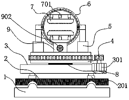
[0028] as attached figure 1 to attach Figure 6 Shown:
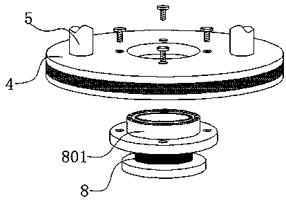
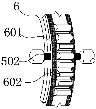
[0029] The present invention provides a multi-angle feeding device: the multi-angle feeding device includes a slide rail 1, a first carrying plate 2, a second carrying plate 3, a turntable 4, a fixed column 5, a movable plate 6, and a clip plate 7, Orientation column 8, guide disc 9, first hydraulic telescopic rod 201, first drive motor 301, side fixed disc 501, positioning pulley 502, positioning rail 601, passive tooth 602, second hydraulic telescopic rod 701, connecting flange 801 , driving gear 901, second drive motor 902;
[0030] A first bearing plate 2 is movably connected above the slide rail 1, a first hydraulic expansion rod 201 is embedded above the first bearing plate 2, and a second bearing plate 3 is welded on the other side of the first hydraulic expansion rod 201. The central part of the plate 3 is provided with a directional column 8 integratedly, and the external rotation of the directional column 8 ...
PUM
 Abstract
Description
Claims
Application Information