Vacuum sweeper dust bin with multistage dust-fall function

A vacuum cleaner and dust reduction technology, which is applied in road cleaning, construction, cleaning methods, etc., can solve the problems of uneven ash falling in the dust box, inability to sprinkle water, and heavy manual workload.

Pending Publication Date: 2019-02-19
HUBEI JULI AUTOMOTIVE TECH CO LTD
View PDF0 Cites 3 Cited by
  • Summary
  • Abstract
  • Description
  • Claims
  • Application Information

AI Technical Summary

Problems solved by technology

Large-scale cleaning sites such as urban sanitation, ports, highways, coal mines and cement plants, etc., are time-consuming and laborious if they are cleaned manually. In order to solve the above problems, a sweeper was born, but due to the limitations of the sweeper For example, in the northern region, it is cold in winter and water cannot be sprinkled. The dust is flying when the sweeper is working, causing secondary pollution to the atmosphere. When the sweeper is cleaning, the brushes are severely worn, replaced frequently, and the manual workload is large. A series of problems, now the sweeper is gradually being replaced by the vacuum cleaner
[0003] The dust box of the existing vacuum cleaner generally has the functions of collecting, sieving and filtering garbage, but lacks effective control and dust reduction treatment for the fine dust particles after sieving, which affects the ventilation volume of the filtration system and reduces the operating efficiency , at the same time, it also causes uneven ash in the dust box, and it is not easy to unload it at one time when unloading

Method used


Image

  • Vacuum sweeper dust bin with multistage dust-fall function
  • Vacuum sweeper dust bin with multistage dust-fall function
  • Vacuum sweeper dust bin with multistage dust-fall function

Examples


Embodiment Construction

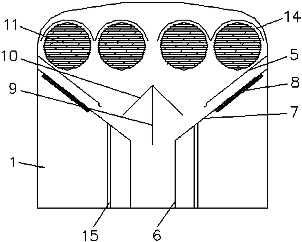
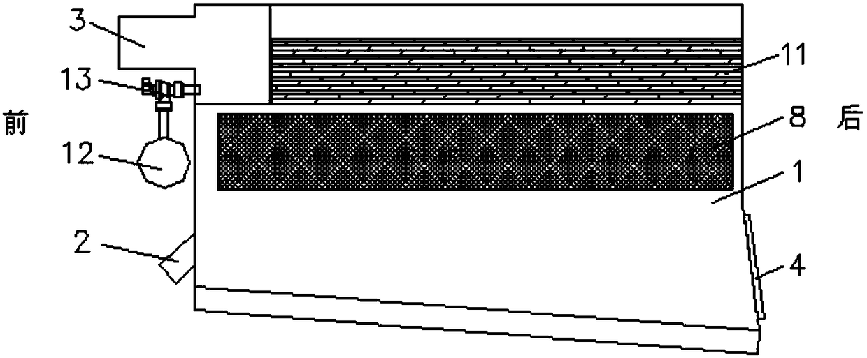
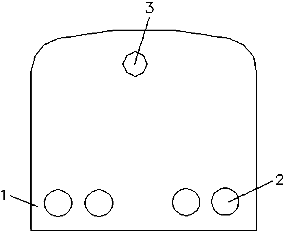
[0032] The principles and features of the present invention are described below in conjunction with the accompanying drawings, and the examples given are only used to explain the present invention, and are not intended to limit the scope of the present invention.

[0033] Such as Figure 1 to Figure 4 As shown, the present invention provides a dust collection car dust box with multi-stage dust reduction function, comprising a box body 1, a plurality of air inlets 2 are provided at the lower part of the front end of the box body 1, and the air inlets 2 are arranged on both sides near the front end, located at The air inlets 2 on both sides are respectively connected with the compartments on both sides of the box body 1. Each air inlet 2 is connected with a suction pipe, and the lower end of the suction pipe is close to the ground; 3. The pipe is connected with the fan, and the fan works to pump out the gas in the box 1 to form a negative pressure in the box 1, so that the garba...


PUM


Abstract

The invention relates to a vacuum sweeper dust bin with a multistage dust-fall function. The vacuum sweeper dust bin comprises a box, multiple air inlets are formed in the lower portion of the front end of the box, an air inlet is formed in the upper portion of the front end of the box, the box is internally provided with two bin separating plates, each bin separating plate comprises a vertical part and an inclined part, the two vertical parts are parallel to each other and are arranged in the long side direction of the box, the vertical parts are vertically arranged, the lower sides of the vertical parts are fixed to the bottom wall of the box, the lower sides of the inclined parts are connected with the upper sides of the vertical parts, the portion between the two vertical parts and theinclined parts divide the box into three mutually independent branch bins, meshed dust-fall mechanisms are arranged between the inclined part and the corresponding side walls of the box, a guide plate is arranged on the upper portion of each dust-fall mechanism, a spoiler component is arranged between the two guide plates, and a filter mechanism is arranged on the upper portion of the spoiler component. The vacuum sweeper dust bin has the advantages that the airflow moving direction is effectively controlled, multistage dust fall is achieved, and then garbage is poured thoroughly all at once.

Description

technical field [0001] The invention relates to the technical field of dust collection vehicles, in particular to a dust box of a dust collection vehicle with a multi-stage dust reduction function. Background technique [0002] With the continuous development of the country and the continuous progress of the society, our requirements for the environment far exceed the previous requirements. Large-scale cleaning sites such as urban sanitation, ports, highways, coal mines and cement plants, etc., are time-consuming and labor-intensive if they are cleaned manually. In order to solve the above problems, a sweeper was born. For example, in the northern region, it is cold in winter and water cannot be sprinkled. The dust is flying when the sweeper is working, causing secondary pollution to the atmosphere. When the sweeper is cleaning, the brushes are severely worn, replaced frequently, and the manual workload is large. A series of problems, now the sweeper is gradually being repl...

Claims


Application Information

Patent Timeline
Patent Type & Authority Applications(China)
IPC IPC(8): E01H1/08
CPCE01H1/0836
Inventor 徐浩博
Owner HUBEI JULI AUTOMOTIVE TECH CO LTD
Why Eureka
Try Eureka