A dust removal device for coal mine safety

A dust removal device and coal mine safety technology, which is applied in safety devices, mining devices, dust prevention, etc., can solve problems such as unsatisfactory dust removal effect, achieve the effect of shortening dust removal time, improving dust removal efficiency, and good dust removal effect

Active Publication Date: 2020-11-13
曾美枝
View PDF7 Cites 0 Cited by
  • Summary
  • Abstract
  • Description
  • Claims
  • Application Information

AI Technical Summary

Problems solved by technology

[0003] The purpose of the present invention is to provide a dust removal device for coal mine safety, which has the advantage of good dust removal effect, and solves the problem of unsatisfactory dust removal effect of common coal mine safety dust removal devices

Method used


Image

  • A dust removal device for coal mine safety
  • A dust removal device for coal mine safety
  • A dust removal device for coal mine safety

Examples


Embodiment 1

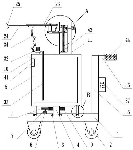
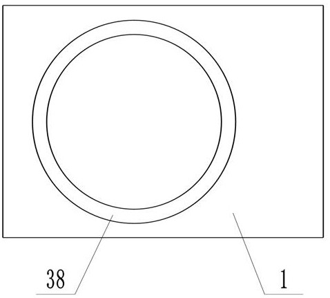
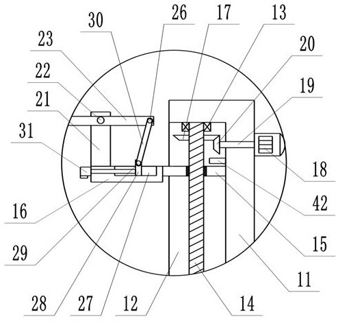
[0024] see Figure 1-4, a dust removal device for coal mine safety, comprising a bottom plate 1, moving wheels 2 are arranged at the four corners of the bottom of the bottom plate 1, a first rolling bearing 3 is fixedly connected in the groove at the midpoint of the top of the bottom plate 1, and the inside of the first rolling bearing 3 A support shaft 4 is movably connected, and the top of the support shaft 4 runs through the first rolling bearing 3 and extends to the outside of which a water tank 5 is fixedly connected. The top of the bottom plate 1 and the position corresponding to the water tank 5 are provided with an annular chute 38, and the left and right sides of the bottom of the water tank 5 And the positions corresponding to the annular chute 38 are all fixedly connected with supporting legs 39, the bottom of the supporting legs 39 runs through the annular chute 38 and extends to its inside, the groove at the bottom of the supporting legs 39 is movably connected wit...

Embodiment 2

[0027] A lot of parts are arranged on the top of the water tank 5, and its center of gravity is often not at its geometric center. If the water tank 5 is driven to rotate through the support shaft 4 in Embodiment 1, the water tank 5 will inevitably produce centrifugal rotation, and this centrifugal rotation A shearing force in the horizontal direction will be generated on the supporting rotating shaft 4 , thereby increasing the probability of damaging the supporting rotating shaft 4 .

[0028] exist figure 1 On the basis of Figure 5 to Figure 7 , different from Embodiment 1, in this embodiment, an annular chute 38 is provided at the top of the bottom plate 1 and corresponding to the position of the water tank 5, and an upper annular plate 45 is provided below the water tank 5, and the water tank 5 is fixedly connected to the upper annular plate 45, It can also be connected by the supporting legs 39 shown in Embodiment 1. The upper annular plate 45 is arranged on the bottom ...


PUM


Abstract

The invention discloses a dust removal device for coal mine safety. The dust removal device for the coal mine safety comprises a bottom plate, moving wheels are arranged at the four corners of the bottom of the bottom plate, and a first rolling bearing is fixedly connected to the inside of a groove at the middle point of the top of the bottom plate. Through the mutually cooperation of the first rolling bearing, a supporting rotating shaft, a water tank, a rotating motor, a rotating shaft, a driving gear, a driven gear, a fixed seat, a thread rod, a thread sleeve, a supporting plate, a driven bevel gear, a forward and reverse motor, a forward and reverse rotating shaft, a driving bevel gear, a fixed plate, a first fixed shaft, a fixed rod, a water spraying pipe, an atomizing nozzle, a second fixed shaft, a slide slot, a sliding block, a third fixed shaft, a connecting rod, an electric push rod and a hose, a good dust removal effect is realized; and by adjusting the angle of atomizing nozzle, the scope of dust removal is increased, the dust removal efficiency is improved, the dust removal time is greatly shortened, the normal operation of coal mining is guaranteed, and great convenience to coal mine mining enterprises is achieved.

Description

technical field [0001] The invention relates to the technical field of coal mine dust removal, in particular to a coal mine safety dust removal device. Background technique [0002] Coal mines are areas where human beings exploit coal resources in coal-rich mining areas, and are generally divided into underground coal mines and open-pit coal mines. When the coal seam is far away from the surface, it is generally selected to excavate the coal by digging the roadway underground, which is an underground coal mine. When the distance between the coal seam and the surface is very short, it is generally chosen to directly strip the surface soil layer to excavate coal, which is an open-pit coal mine. A large amount of dust will be generated in all links of the coal mining process, which not only pollutes the environment, but also seriously affects the health of coal miners. Coal workers have become a high-risk group susceptible to pneumoconiosis, so water spraying and dust removal ...

Claims


Application Information

Patent Timeline
Patent Type & Authority Patents(China)
IPC IPC(8): E21F5/04E21F17/00
CPCE21F5/04E21F17/00
Inventor 王永
Owner 曾美枝
Why Eureka
Try Eureka