Optical frame

An optical frame and mirror frame technology, applied in the optical field, can solve problems such as poor stability of the mirror frame, and achieve the effects of convenient collimation, high-precision laser output, and increased long-term stability

Active Publication Date: 2019-02-19
AVIC BEIJING AERONAUTICAL MFG TECH RES INST
View PDF12 Cites 7 Cited by
  • Summary
  • Abstract
  • Description
  • Claims
  • Application Information

AI Technical Summary

Problems solved by technology

[0007] In view of this, the present application provides a method for solving the problem of poor long-term stability of traditional manual optical adjustment frames in the prior art.

Method used


Image

  • Optical frame
  • Optical frame
  • Optical frame

Examples


Embodiment Construction

[0031] In order to make the technical problems, technical solutions and advantages to be solved by the embodiments of the present invention clearer, the following will describe in detail with reference to the drawings and specific embodiments.

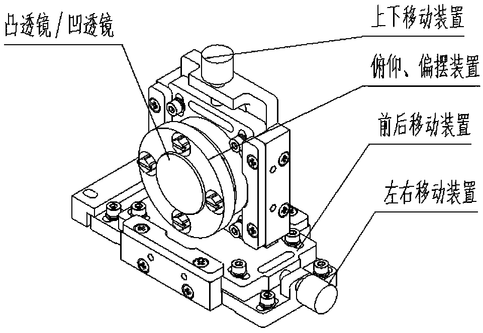
[0032] The technical scheme adopted in the present invention is: a multi-degree-of-freedom optical frame design for optical path adjustment. It mainly includes: pitching, yaw device, up and down moving device, left and right moving device and forward and backward moving device, such as figure 1 As shown, it is a schematic structural diagram of a multi-degree-of-freedom optical frame for optical path adjustment provided by an embodiment of the present invention. Put the optical frame into the light path, adjust the pitch and deflection device to change the incident angle of light from the convex lens / concave lens; adjust the up and down, left and right movement device can cause the light to enter from the paraxial axis of the convex len...


PUM


Abstract

The invention provides a multiple degree of freedom optical frame for optical path adjustment. The frame comprises a pitch and yaw device, an up and down moving device, a left and right moving device,and a front and rear moving device. An adjustment frame provided by the invention has a modular characteristic. The adjustment frame suitable for a reflecting mirror or a transmission mirror can be produced by intercepting a key structure thereof. The shortcomings of a manual optical adjustment frame provided by the traditional technology are overcome. A reset mechanism is improved by using a screw fixing mode instead of return springs. When the optical path adjustment is completed, a moving plate and a fixing plate of a frame body are connected by screws, so as to increase the long-term stability of the frame. The reset mechanism can be used as an engineering application of laser devices. The scheme is low in cost and easy to realize. By using the adjustment frame, an optical path of a laser can be debugged and maintained, and the laser can be collimated quickly and conveniently to obtain a high-precision laser output.

Description

technical field [0001] The invention relates to the field of optical technology, in particular to an optical mirror frame for optical path adjustment. Background technique [0002] Optical path adjustment is an important part in the laser field. Its main function is to adjust the lens according to the azimuth, pitch and angle of the optical path, so that the optical path propagates in a predetermined direction. [0003] Traditionally commonly used manual optical adjustment frames are mainly divided into main parts (moving plate, fixed plate), driving mechanism (thread pair), guiding mechanism (guide rail), reset mechanism (return spring), locking mechanism and other parts. Its working principle is that the screw pair of the driving mechanism converts the rotary motion into the linear movement of the moving plate to drive the movement of the lens. During the adjustment process, the pressure generated by the screw pair driving the moving plate and the elastic force generated b...

Claims


Application Information

Patent Timeline
Patent Type & Authority Applications(China)
IPC IPC(8): G02B7/02
CPCG02B7/023
Inventor 唐玮王秋实胡文华何文伟
Owner AVIC BEIJING AERONAUTICAL MFG TECH RES INST
Why Eureka
Try Eureka