

Spine shell resetter
A resetter and shell technology, applied in the field of medical devices, can solve problems such as simple structure, long recovery time, and easy recurrence, and achieve the effect of reducing recurrence, reducing recovery time, and improving comfort
- Summary
- Abstract
- Description
- Claims
- Application Information
AI Technical Summary
Problems solved by technology
Method used
Image

Examples
Embodiment Construction
[0018] The technical solutions in the embodiments of the present invention will be clearly and completely described below in conjunction with the accompanying drawings in the embodiments of the present invention. Obviously, the described embodiments are only some of the embodiments of the present invention, not all of them. Based on the embodiments of the present invention, all other embodiments obtained by persons of ordinary skill in the art without creative work all belong to the protection scope of the present invention.
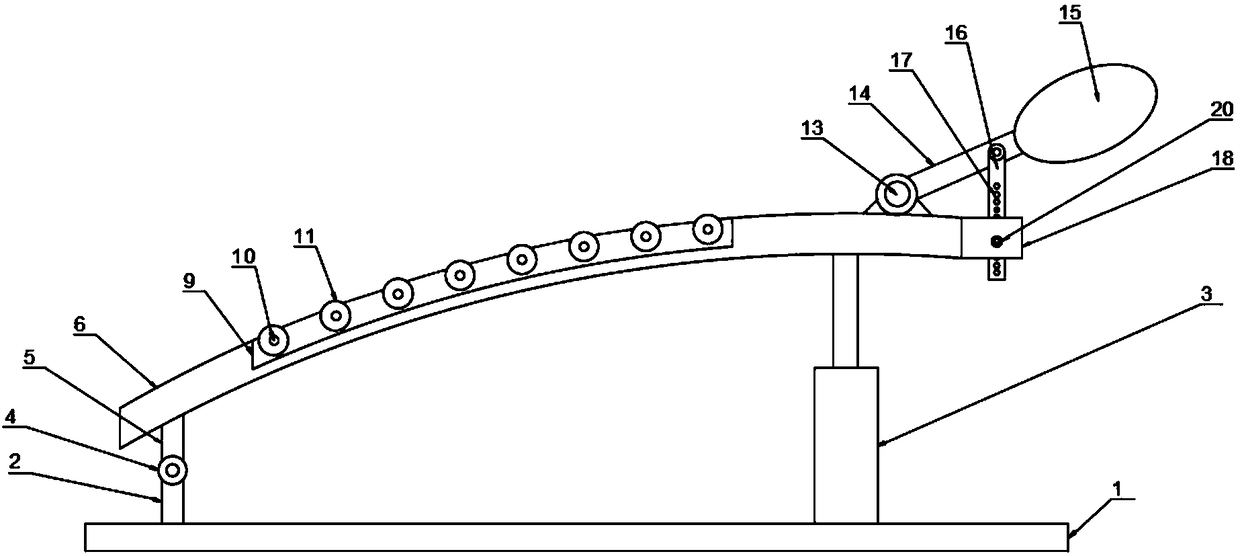
[0019] The present invention provides such as figure 1 A kind of spinal shell restorer shown comprises base plate 1, and described base plate 1 top is provided with first support rod 2, and described first connecting rod side is provided with elevating rod 3, and described first support rod 2 top is provided with There is a first connecting bearing 4, the top of the first connecting bearing 4 is provided with a second connecting rod 5, the top of the sec...
PUM
 Abstract
Description
Claims
Application Information