Single-galvanometer big-area additive manufacturing laser forming equipment and forming method

A laser forming and additive manufacturing technology, which is applied in the field of additive manufacturing, can solve problems such as intensified spheroidization effect in the splicing area, uneven temperature field distribution, and processing failure, so as to avoid forming failure in the splicing area and avoid coordinated control process , The effect of reducing R&D and manufacturing costs

Pending Publication Date: 2019-02-22
天津镭明激光科技有限公司
View PDF7 Cites 1 Cited by
  • Summary
  • Abstract
  • Description
  • Claims
  • Application Information

AI Technical Summary

Problems solved by technology

[0004] The existing multi-galvanometer system technology still has the following technical defects or deficiencies: On the one hand, the segmentation of the three-dimensional model of the multi-laser SLM forming equipment is usually an average segmentation, but the solid area to be melted by the laser is not evenly distributed in space, such as It is full of thin-walled, curved columnar supports and other special-shaped structures, resulting in not only a huge difference in the area of ​​the solid part to be processed in each galvanometer scanning area, but also an extremely uneven distribution of the temperature field.
In addition, at the junction of adjacent galvanometer scanning areas, a splicing area of ​​a certain width is required. Due to the inconsistent scanning time of adjacent laser galvanometer scanning systems, the splicing area may have aggravated spheroidization effects or even processing failures. Therefore, multi-vibration How to efficiently coordinate the work of the mirror system has always been an urgent problem to be solved
In addition, optical components such as lasers and galvanometers are the most expensive in laser forming equipment, so the multi-galvanometer system directly doubles the cost of equipment

Method used


Image

  • Single-galvanometer big-area additive manufacturing laser forming equipment and forming method
  • Single-galvanometer big-area additive manufacturing laser forming equipment and forming method
  • Single-galvanometer big-area additive manufacturing laser forming equipment and forming method

Examples


Embodiment 1

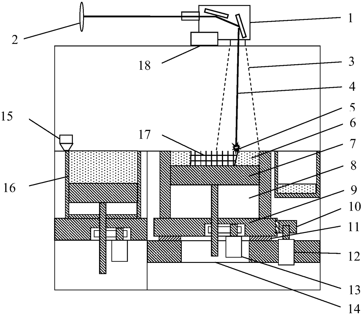
[0045] see figure 1 and figure 2 , this embodiment provides a laser forming equipment for large-format additive manufacturing with a single vibrating mirror, including a vibrating mirror 1, a point light source 2, a forming chamber 8, a forming substrate 7, a transmission mechanism 13, and a fixed platform 14. The vibrating mirror 1 is installed on the On the mirror fixing table 18, the forming chamber 8 can rotate around its central axis, so that the scanning area of ​​the laser on the forming surface is rotated relative to the forming surface.

[0046] As a preferred embodiment, the bottom of the forming chamber 8 is equipped with a rotating assembly that can rotate the forming chamber around its central axis. During the laser forming process, the forming chamber drives the forming substrate to rotate axially, and the forming surface rotates, so that the scanning The diameter of the field is doubled, and the area of ​​the scanning field is quadrupled.

[0047] As a furthe...

Embodiment 2

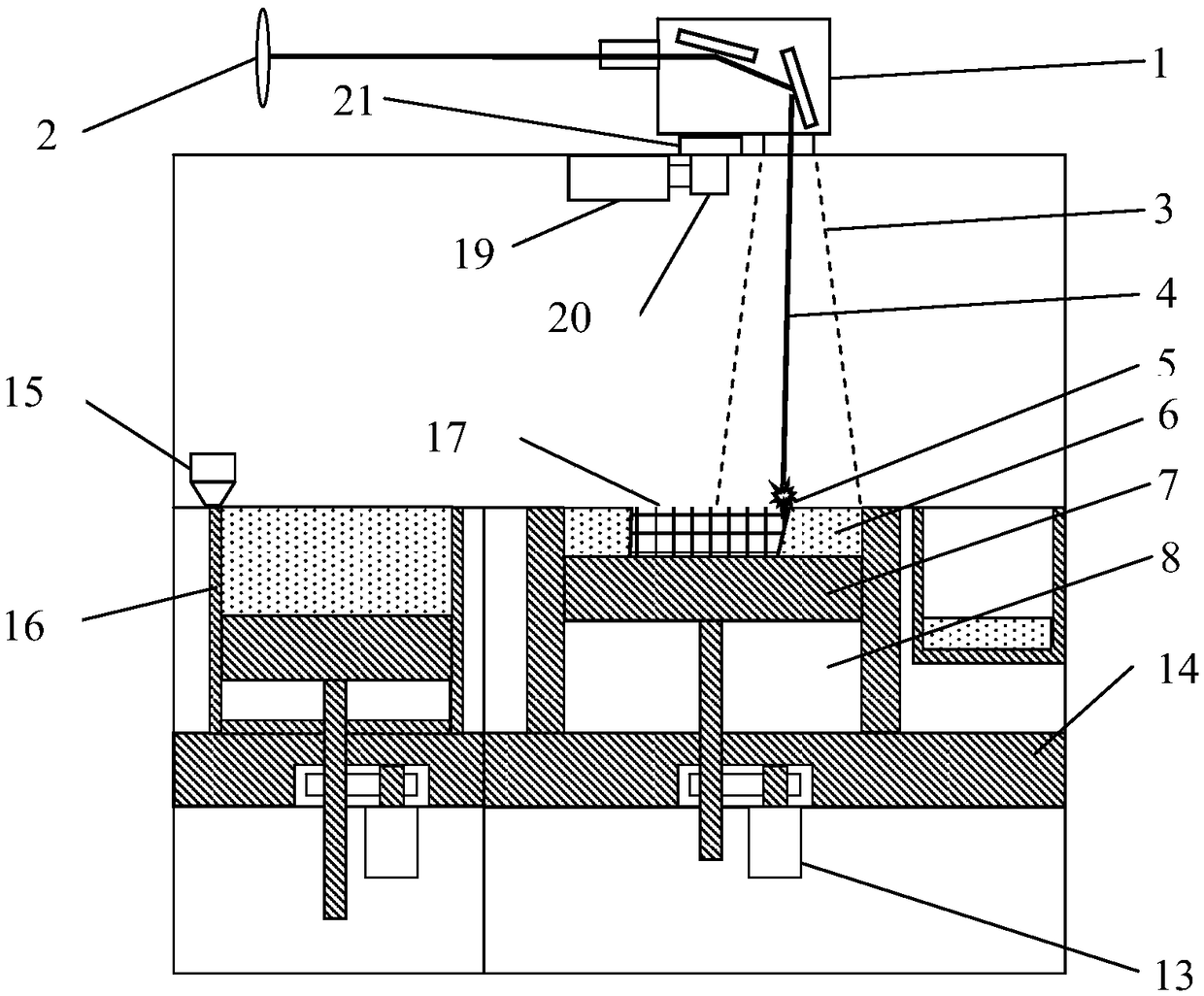
[0051] see image 3 and Figure 4 , this embodiment provides a laser forming equipment for large-format additive manufacturing with a single vibrating mirror, including a vibrating mirror 1, a point light source 2, a forming chamber 8, a forming substrate 7, a transmission mechanism 13, and a fixed platform 14, and the vibrating mirror 1 can be formed around The central axis of the bin 8 rotates, so that the scanning area of ​​the laser on the forming surface is rotated relative to the forming surface.

[0052] As a preferred embodiment, the bottom of the vibrating mirror 1 is equipped with a rotating device that can rotate the vibrating mirror around the central axis of the forming chamber 8. When the vibrating mirror is rotated during the laser forming process, the scanning area of ​​the single vibrating mirror on the forming substrate will rotate. , so that the diameter of the scanning area is doubled, and the area of ​​the scanning area is quadrupled.

[0053] As a furth...

Embodiment 3

[0056] see figure 1 and Figure 5 , the present embodiment provides a method for forming laser forming equipment using the large-format additive manufacturing laser forming device described in Embodiment 1, comprising the following steps:

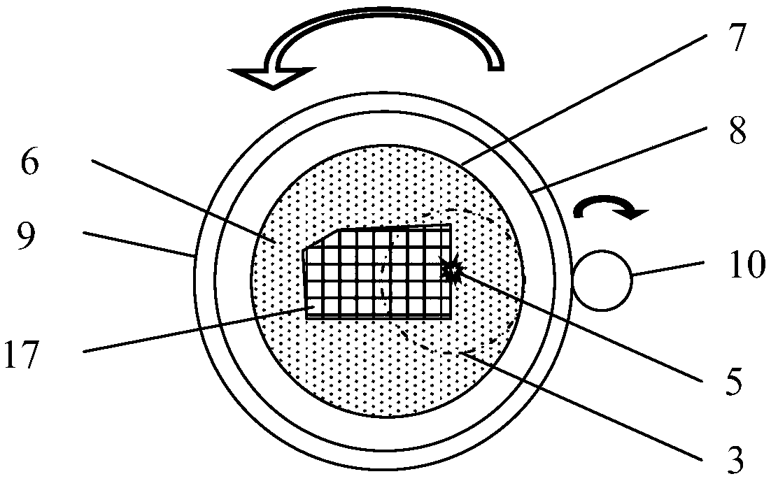
[0057] 1) During the pre-processing laser path planning process of the formed part 17, the scanning area of ​​each layer is fan-shaped, and then the information of the formed part is imported into the numerical control system of the laser forming equipment for laser forming;

[0058] 2) The forming surface laser 5 scans in its laser scanning range 3, and at the same time controls the rotating base 9 to continuously rotate so that the forming surface rotates synchronously;

[0059] 3) The forming surface laser 5 forms a scanning path 27 for each fan-shaped area 26 and scans it. After the forming surface rotates a circle, the central area 25 is scanned separately to complete the laser forming process of the current layer;

[0060] 4) After ...


PUM


Abstract

The invention relates to single-galvanometer big-area additive manufacturing laser forming equipment and a forming method, and belongs to the technical field of additive manufacturing. The equipment comprises a point light source or linear light source, a galvanometer, a lens, a forming bin, a forming substrate, a transmission mechanism and a fixed platform. The galvanometer or the forming bin canrotate around the center axis of the forming bin, so that the scanning area of lasers on a forming surface rotates relative to the forming surface. Particularly, a rotary device capable of enabling the galvanometer to rotate around the center axis of the forming bin is mounted at the bottom of the galvanometer, or a rotary assembly capable of enabling the forming bin to rotate around the center axis of the forming bin is mounted at the bottom of the forming bin. According to the single-galvanometer big-area additive manufacturing laser forming equipment and the forming method, the forming area of the laser forming equipment is four times that of traditional equipment through the single laser galvanometer, the technical problem that the single-light-source forming area of traditional additive manufacturing equipment is limited is solved, the complex coordination control process during work of a multi-laser-galvanometer system is avoided, and meanwhile the problem that forming of a spliced area fails is avoided. The number of core components of the equipment is small, and the development and manufacturing cost of the equipment is reduced.

Description

technical field [0001] The invention belongs to the technical field of additive manufacturing, and in particular relates to a laser forming equipment and a forming method for large-scale additive manufacturing with a single vibrating mirror. Background technique [0002] Selective laser melting (also known as additive manufacturing or metal 3D printing) technology is a new processing method that has emerged in recent years. The raw materials used in this technology are powders of tens to hundreds of microns. During the molding process, Spread the powder evenly on the forming substrate through the powder supply mechanism and the powder spreading mechanism, and then use energy sources such as lasers to melt the powder in a specific geometric shape area on the surface to produce metallurgical bonding, and finally make the parts grow layer by layer to achieve three-dimensional molding. process. [0003] With the popularization and application of this technology, the demand for ...

Claims


Application Information

Patent Timeline
Patent Type & Authority Applications(China)
IPC IPC(8): B22F3/105B33Y10/00B33Y30/00
CPCB33Y10/00B33Y30/00B22F10/00B22F10/28B22F12/226Y02P10/25B22F12/00
Inventor 程锦泽谭鹏刚李澄李广生
Owner 天津镭明激光科技有限公司
Why Eureka
Try Eureka