A bus handrail

A bus and handrail technology, applied in vehicle parts, special positions of vehicles, transportation and packaging, etc., can solve problems such as increased hand grip, wrist damage, and change in grip direction.

Active Publication Date: 2021-08-20
杭州酬催科技有限公司
View PDF5 Cites 0 Cited by
  • Summary
  • Abstract
  • Description
  • Claims
  • Application Information

AI Technical Summary

Problems solved by technology

[0002] At present, the bus is a kind of means of transportation for people to go out, and the handrail of the bus is a device that is convenient for people to hold it by hand, which ensures that the bus is stable when it is running, but the handrail of the current bus is fully grasped by people's hands. And provide support, so that when making a sharp turn, people's center of gravity will be greatly shifted, which will cause people's grasping force to increase instantly, and the direction of the holding force will change instantly, which will cause great damage to the wrist. At the same time, Phenomenon where people get "thrown out" if they don't react in time

Method used


Image

  • A bus handrail
  • A bus handrail
  • A bus handrail

Examples


Embodiment 1

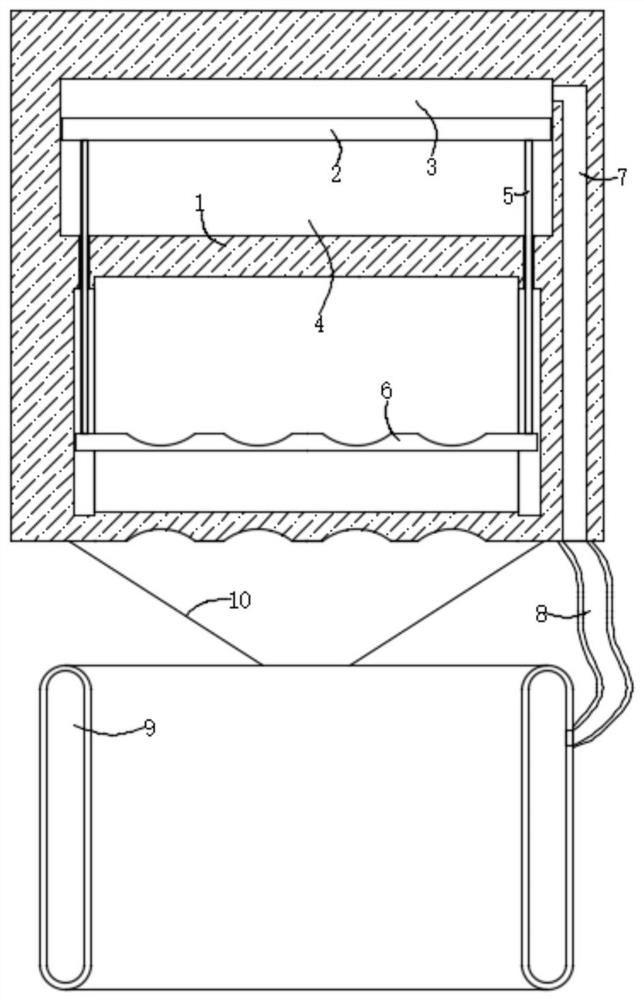
[0019] refer to figure 1 , a bus handrail, comprising a handrail ring 1, a control chamber is provided in the handrail ring 1, a piston 2 is arranged in the control chamber, the piston 2 divides the control chamber into an upper chamber 3 and a lower chamber 4, and the bottom of the piston 2 is fixedly connected There are two extension rods 5, the bottoms of the two extension rods 5 run through the inner side wall of the lower chamber 4 and are fixedly connected with the same handrail rod 6, and the inner side wall of the handrail ring 1 is provided with a chute corresponding to the handrail rod 6;

[0020] It should be noted that: 1, the top of the handrail rod 6 and the bottom of the handrail ring 1 are provided with a plurality of handrail grooves, so that the setting of the handrail grooves is convenient for people to grasp the handrail rod 5 and the bottom of the handrail ring 1; The inner side wall of the chamber 4 is provided with a through opening corresponding to the ...

Embodiment 2

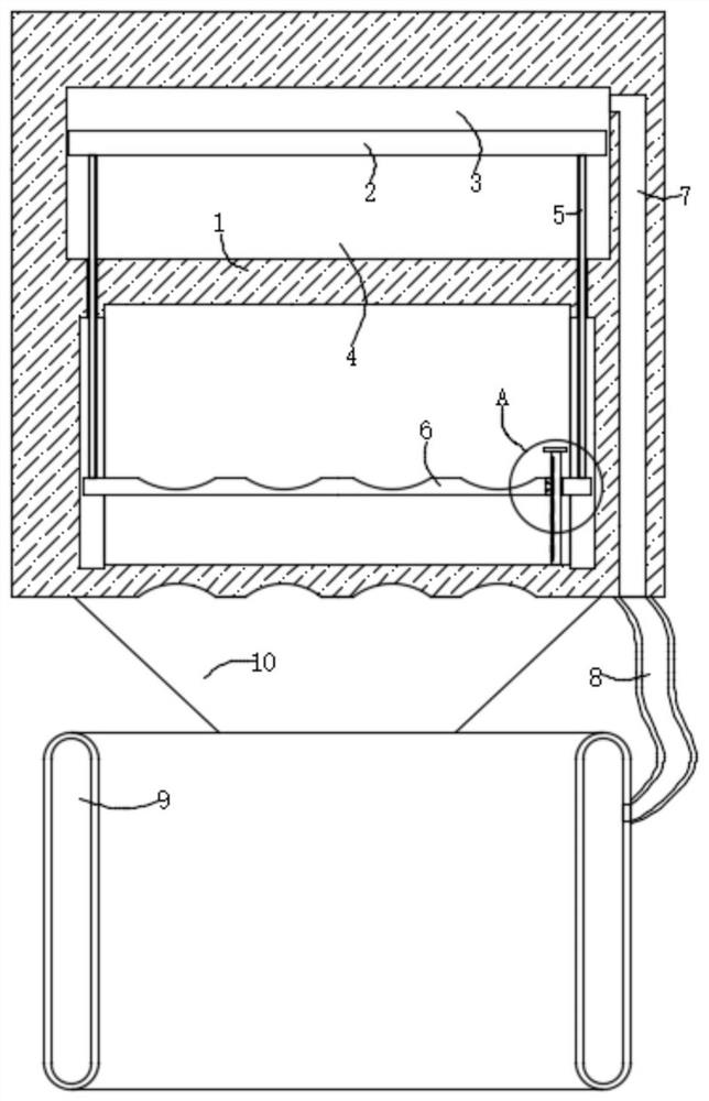
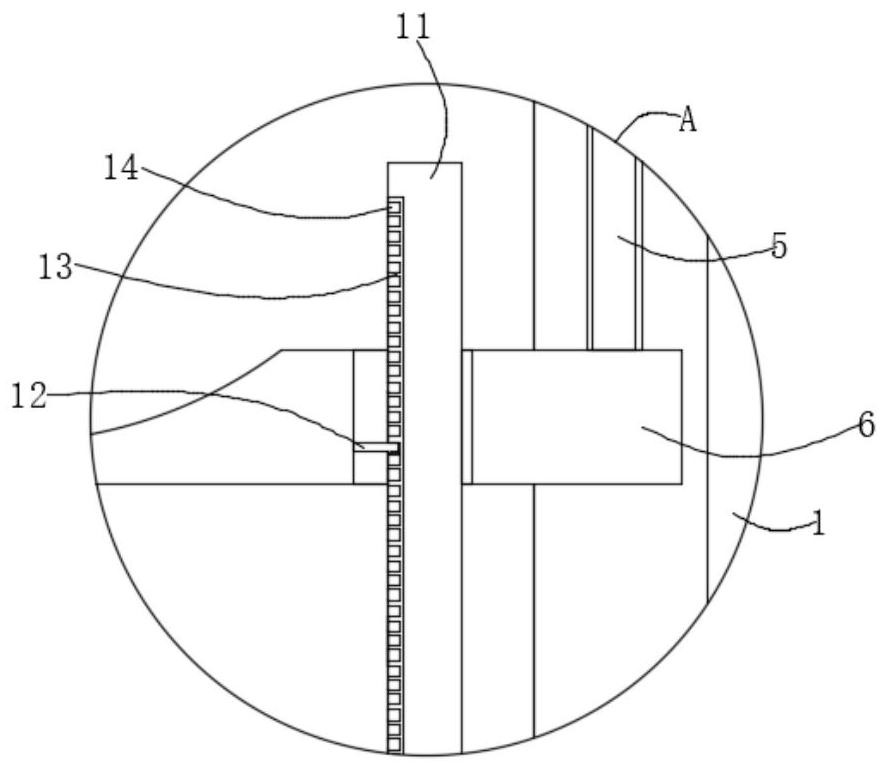
[0026] refer to Figure 2-3 The difference between this embodiment and Embodiment 1 is that the degree of contraction of the hand guard airbag 9 can be controlled, so that it can be adjusted according to the comfort of the passenger, that is, the inner bottom of the armrest ring 1 is rotatably connected with a rotating rod 11, and the upper armrest rod 6 An opening corresponding to the rotating rod 11 is provided, and the inner side wall of the opening is fixedly connected with the limiting rod 12, and the outer wall of the rotating rod 11 is provided with a connecting groove 13 corresponding to the limiting rod 12, which is vertically arranged, and the connecting groove 13 The inner side wall is provided with a plurality of limit grooves 14 arranged horizontally, so that through the cooperation effect of the limit rod 12, the connecting groove 13, the limit groove 14 and the rotating rod 11, the degree of downward movement of the handrail rod 6 is controlled, thereby controlli...


PUM


Abstract

The invention discloses a bus handrail, which comprises a handrail ring, a control chamber is arranged in the handrail ring, a piston is arranged in the control chamber, and the piston divides the control chamber into an upper chamber and a lower chamber. There are two extension rods fixedly connected at the bottom. When the present invention is in use, people's palms pass through the hand guard airbag and hold it on the armrest bar. Due to the grip force, the armrest bar moves downward, and the piston moves downward through the extension rod. In this way, the air pressure in the hand guard airbag It is sucked into the upper cavity, so as to protect the passenger's wrist through the contracted hand guard airbag, avoiding the passenger's wrist injury during sharp turns, and the problem of passengers being "thrown out". Cooperating with the limit groove to control the downward movement of the armrest rod, thereby controlling the shrinkage of the hand guard airbag, which can be self-adjusted according to the thickness of different people's wrists, making people more comfortable.

Description

technical field [0001] The invention relates to the technical field of safety equipment, in particular to a bus handrail. Background technique [0002] At present, the bus is a kind of means of transportation for people to go out, and the handrail of the bus is a device that is convenient for people to hold it by hand, which ensures that the bus is stable when it is running, but the handrail of the current bus is fully grasped by people's hands. And provide support, so that when making a sharp turn, people's center of gravity will be greatly shifted, which will cause people's grasping force to increase instantly, and the direction of the holding force will change instantly, which will cause great damage to the wrist. At the same time, If people don't react in time, it will lead to the phenomenon of people being "thrown out". Contents of the invention [0003] The purpose of the invention is to solve the problems existing in the prior art, and propose a kind of bus handrai...

Claims


Application Information

Patent Timeline
Patent Type & Authority Patents(China)
IPC IPC(8): B60N3/02
CPCB60N3/02B60N3/026
Inventor 张玉梅
Owner 杭州酬催科技有限公司
Why Eureka
Try Eureka