High-resistance anti-collision barrier intercepting device
An anti-collision and high-resistance technology, applied in roads, restricted traffic, roads and other directions, can solve the problems of inflexible movement and slow movement of explosion-proof sliding doors, and achieve the effect of flexible and stable movement, fast movement speed and convenient use
- Summary
- Abstract
- Description
- Claims
- Application Information
AI Technical Summary
Problems solved by technology
Method used
Image
Examples
Embodiment 1
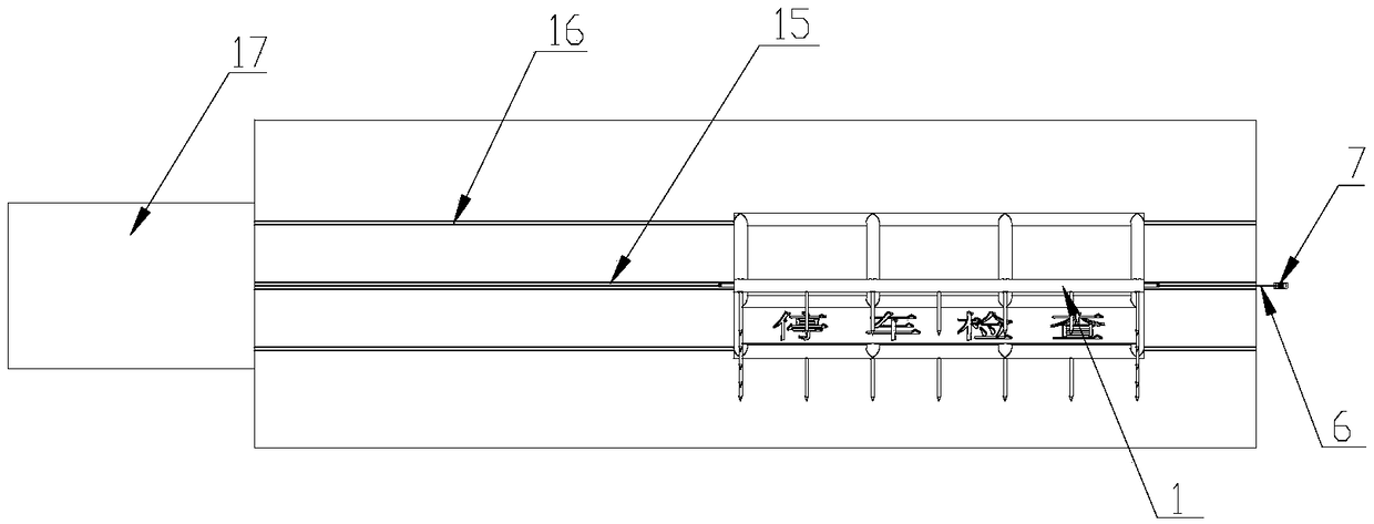
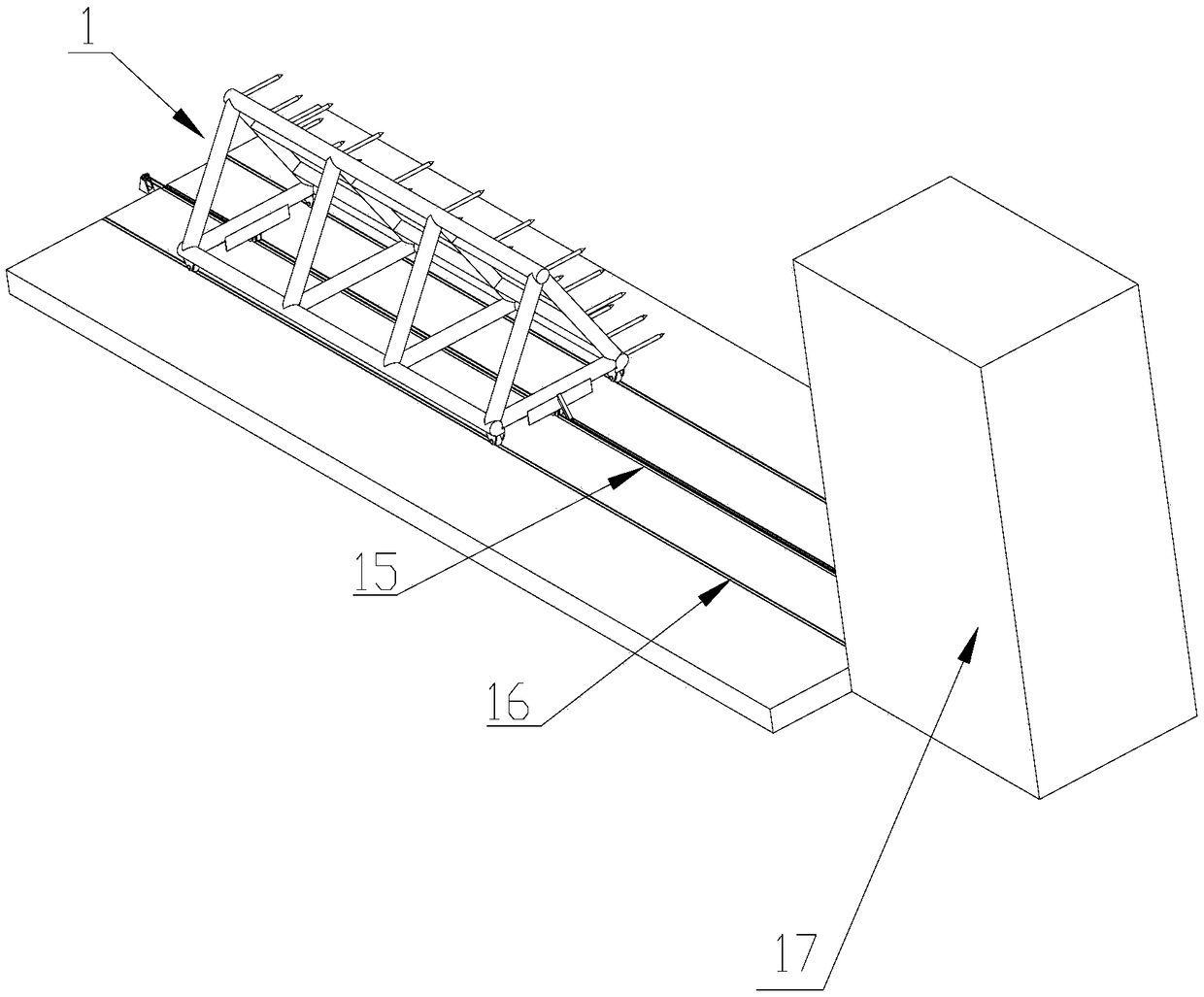
[0030] like Figure 1-Figure 9 The shown high-resistance anti-collision barrier device includes an explosion-proof sliding door 1, a drive motor 2 and a guide rail 3 for fixing on the ground. The guide rail 3 is arranged along the left and right directions, and the explosion-proof sliding door 1 The bottom of the front support rod 1-1 and the rear support rod 1-2 are provided with a plurality of directional wheels 4, the bottom of the explosion-proof sliding door 1 and the guide rail 3 constitute a horizontal movement pair, and the drive motor 2 is used for The explosion-proof sliding door 1 is driven to move along the length direction of the guide rail 3 .
[0031]The explosion-proof sliding door 1 includes a front support rod 1-1, a rear support rod 1-2, a left support rod 1-3, a right support rod 1-4, an upper support rod 1-5, a first left connecting rod 1- 6. The second left connecting rod 1-7, the first right connecting rod 1-8 and the second right connecting rod 1-9, th...
Embodiment 2
[0037] This embodiment is a further improvement on the basis of Embodiment 1. Compared with Embodiment 1, this embodiment is also provided with a second fixed pulley 9 and a third fixed pulley 10. The second fixed pulley 9 and the third fixed pulley The three fixed pulleys 10 respectively adopt the second fixed pulley mount and the third fixed pulley mount to be arranged on the ground on the side away from the first fixed pulley 7, the first fixed pulley 7, the second fixed pulley 9 and the first fixed pulley The three fixed pulleys 10 are located on the same vertical plane, and the rope 6 passes through the bottom of the explosion-proof sliding door 1 and then walks around the second fixed pulley 9, the driving wheel 8 and the third fixed pulley 10 and connects with the explosion-proof sliding door 1. The left hook is connected, and the present application preferably has a rope hole (not shown) that runs through the left and right sides of the third fixed pulley 10 on the thir...
Embodiment 3
[0039] This embodiment is further improved on the basis of Embodiment 2. Compared with Embodiment 2, the guide rail 3 described in this embodiment has a through hole along its length direction, and the rope 6 passes through the passage on the guide rail 3. It passes through the hole and can move in the through hole. The structure of the rest of this embodiment is the same as that of Embodiment 2, for details, reference may be made to Embodiment 2, and details will not be described in this embodiment.
PUM
 Abstract
Description
Claims
Application Information
 - R&D
- Intellectual Property
- Life Sciences
- Materials
- Tech Scout
- Unparalleled Data Quality
- Higher Quality Content
- 60% Fewer Hallucinations
Browse by: Latest US Patents, China's latest patents, Technical Efficacy Thesaurus, Application Domain, Technology Topic, Popular Technical Reports.
© 2025 PatSnap. All rights reserved.Legal|Privacy policy|Modern Slavery Act Transparency Statement|Sitemap|About US| Contact US: help@patsnap.com


