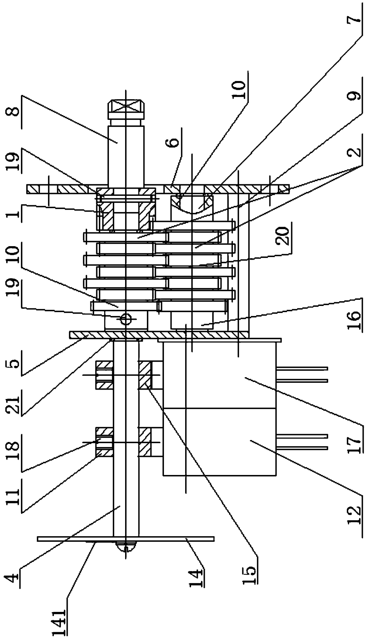
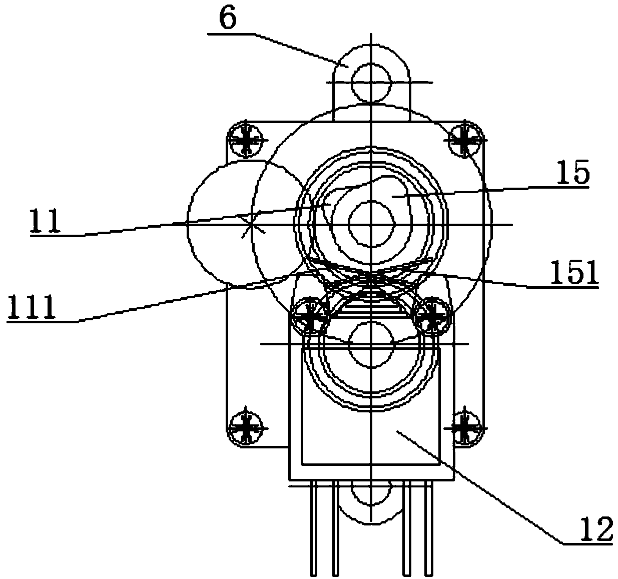
Control mechanism of multi-rotation valve drive device

A technology of driving device and control mechanism, applied in the direction of valve device, valve operation/release device, engine components, etc., can solve the problem of valve idling monitoring not in place, and achieve simple structure, increased contact area and high stability Effect

Pending Publication Date: 2019-02-22
天津科利华阀控设备有限公司
View PDF9 Cites 2 Cited by
  • Summary
  • Abstract
  • Description
  • Claims
  • Application Information

AI Technical Summary

Problems solved by technology

[0004] The problem to be solved by the present invention is to provide a control mechanism for a multi-turn valve driving device, which can simultaneously perform opening indication and stroke control, with good stability, real-time monitoring of the movement state of the valve, and avoiding the situation that the idling monitoring of the valve is not in place. safety

Method used


Image

  • Control mechanism of multi-rotation valve drive device
  • Control mechanism of multi-rotation valve drive device
  • Control mechanism of multi-rotation valve drive device

Examples


Embodiment Construction

[0024] It should be noted that, in the case of no conflict, the embodiments of the present invention and the features in the embodiments can be combined with each other.

[0025] In describing the present invention, it should be understood that the terms "center", "longitudinal", "transverse", "upper", "lower", "front", "rear", "left", "right", " The orientations or positional relationships indicated by "vertical", "horizontal", "top", "bottom", "inner" and "outer" are based on the orientations or positional relationships shown in the drawings, and are only for the convenience of describing the present invention and Simplified descriptions, rather than indicating or implying that the device or element referred to must have a particular orientation, be constructed and operate in a particular orientation, and thus should not be construed as limiting the invention. In addition, the terms "first", "second", etc. are used for descriptive purposes only, and should not be understood ...


PUM


Abstract

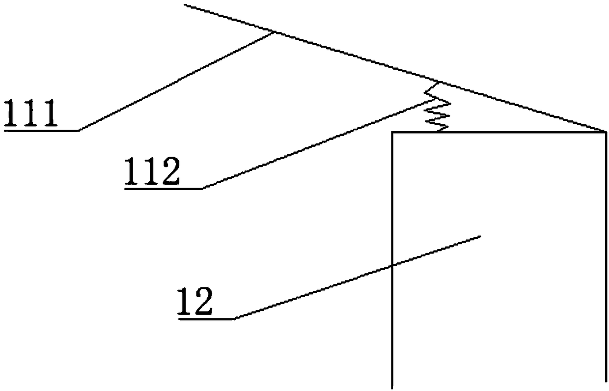
The invention provides a control mechanism of a multi-rotation valve drive device and belongs to the field of valves. The control mechanism comprises an upper plate and a lower plate which are arranged in parallel. A drive shaft and a small shaft are perpendicularly arranged between the upper plate and the lower plate, and the axis of the drive shaft is parallel to the axis of the small shaft. Oneend of the drive shaft protrudes out of the lower plate to be connected with the input end of a valve. Transmission wheel combinations with different speed reduction ratios are arranged between the drive shaft and the small shaft. The end, far away from the lower end, of the upper plate is provided with a pointer shaft, the rotating angle of the pointer shaft is consistent with that of a valve rod, and the pointer shaft is provided with a first plate cam and a second plate cam. The center line of the first plate cam and the center line of the second plate cam are crossed. A first microswitchis arranged corresponding to the high point of the first plate cam, a second microswitch is arranged corresponding to the high point of the second plate cam, and the first microswitch and the second microswitch are electrically connected with a control center. The end, far away from the upper plate, of the pointer shaft is fixedly provided with a pointer board which can display the rotating angleof the valve rod. The control mechanism is stable in performance, and automatic glue scraping can be achieved.

Description

technical field [0001] The invention belongs to the field of valves and relates to a control mechanism of a multi-turn valve drive device. Background technique [0002] The valve is a pipeline accessory used to open and close the pipeline, control the flow direction, adjust and control the parameters (temperature, pressure and flow) of the conveying medium, and is a control component in the fluid conveying system. It can be used to control the flow of various types of fluids such as air, water, steam, various corrosive media, mud, oil, liquid metal and radioactive media. It is necessary to choose valves of different models and specifications, and the choice should be made according to the actual situation. [0003] For multi-stage rotary valves, during use, the operating handle is on the outside and at the upper end, and it is impossible to monitor the specific position and opening of the valve in real time, so it is difficult to monitor the actual working status of the val...

Claims


Application Information

Patent Timeline
Patent Type & Authority Applications(China)
IPC IPC(8): F16K31/53F16K31/524F16K37/00
CPCF16K31/524F16K31/53F16K37/0008
Inventor 王文付丛津毅王子申
Owner 天津科利华阀控设备有限公司
Why Eureka
Try Eureka