Connecting rod clamping mechanism and injection molding machine comprising same

A connecting rod locking and mold locking technology, which is applied in the field of injection molding machinery, can solve the problems of inconvenient maintenance, fire, and large wear of the five-point connecting rod, and achieve the effects of simple and convenient maintenance, increasing the contact surface, and compensating for mechanical wear

Pending Publication Date: 2019-02-26
宁波云上塑料机械有限公司
View PDF1 Cites 2 Cited by
  • Summary
  • Abstract
  • Description
  • Claims
  • Application Information

AI Technical Summary

Problems solved by technology

[0004] However, since the five-point connecting rod of the above-mentioned invention wears a lot and the oil cylinder assembly is arranged on one side of the fixed plate, when this mechanism is used on an injection molding machine, since this side is usually a heating and processing area, the temperature is higher, once the oil leaks It is more likely to cause a fire in this high-temperature area. On the other hand, the spatial structure of this area is tight. Once the equipment fails, maintenance is inconvenient.

Method used


Image

  • Connecting rod clamping mechanism and injection molding machine comprising same
  • Connecting rod clamping mechanism and injection molding machine comprising same
  • Connecting rod clamping mechanism and injection molding machine comprising same

Examples


Embodiment 1

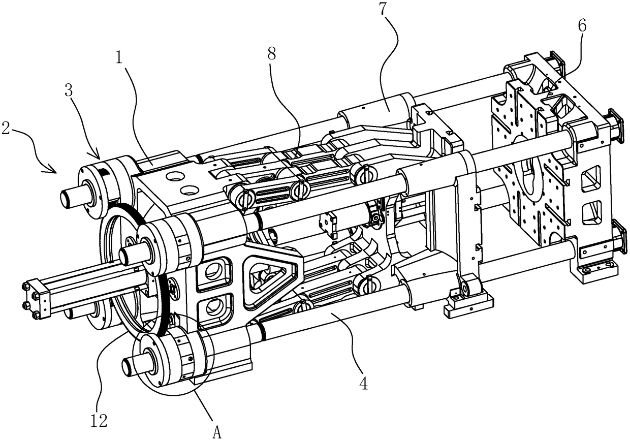
[0036] Specifically, the driving member 11 can be an oil cylinder or a roller screw. The oil cylinder is suitable for providing small torque, while the roller screw is suitable for providing high torque. In this embodiment, a five-point linkage mechanism is adopted. After the driving member 11 is connected with the formwork hinge assembly 8, it is used to expand the five-point linkage mechanism and drive the movable formwork 7 to the mold closing position to achieve a self-locking state.

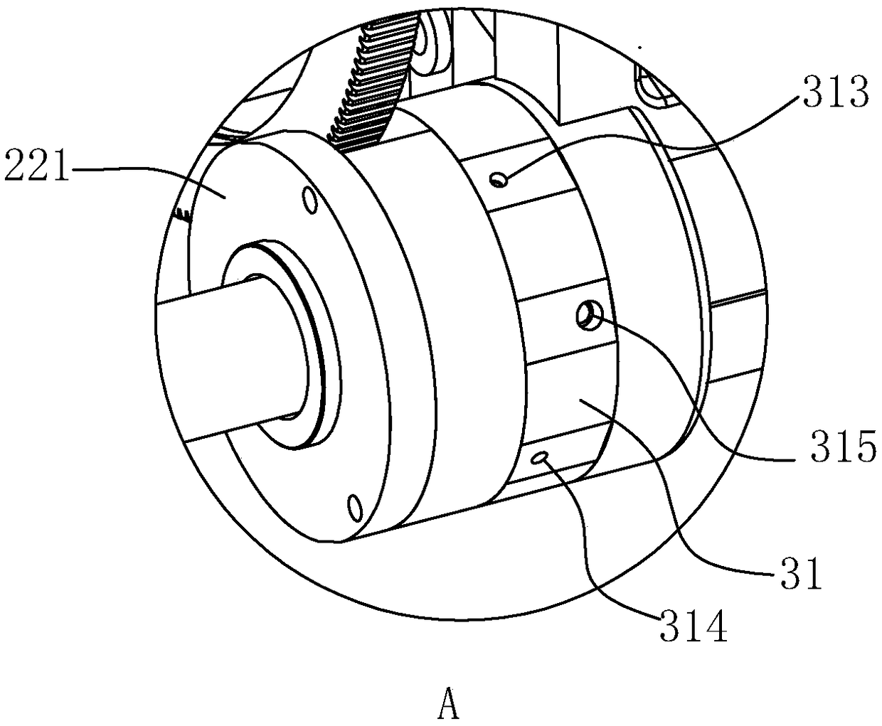
[0037] combined with figure 2 and 3 The mold clamping cylinder assembly 3 includes an oil cylinder body 31 extending outside the base plate 1. The oil cylinder body 31 is located at the position where the outer mold clamping tie rod 4 of the base plate 1 passes through. The oil cylinder body 31 is fixed to the base plate 1 in this embodiment. The connection, of course, can also be integrally formed with the substrate 1 as another implementation manner of this embodiment. The shape of the ...

Embodiment 2

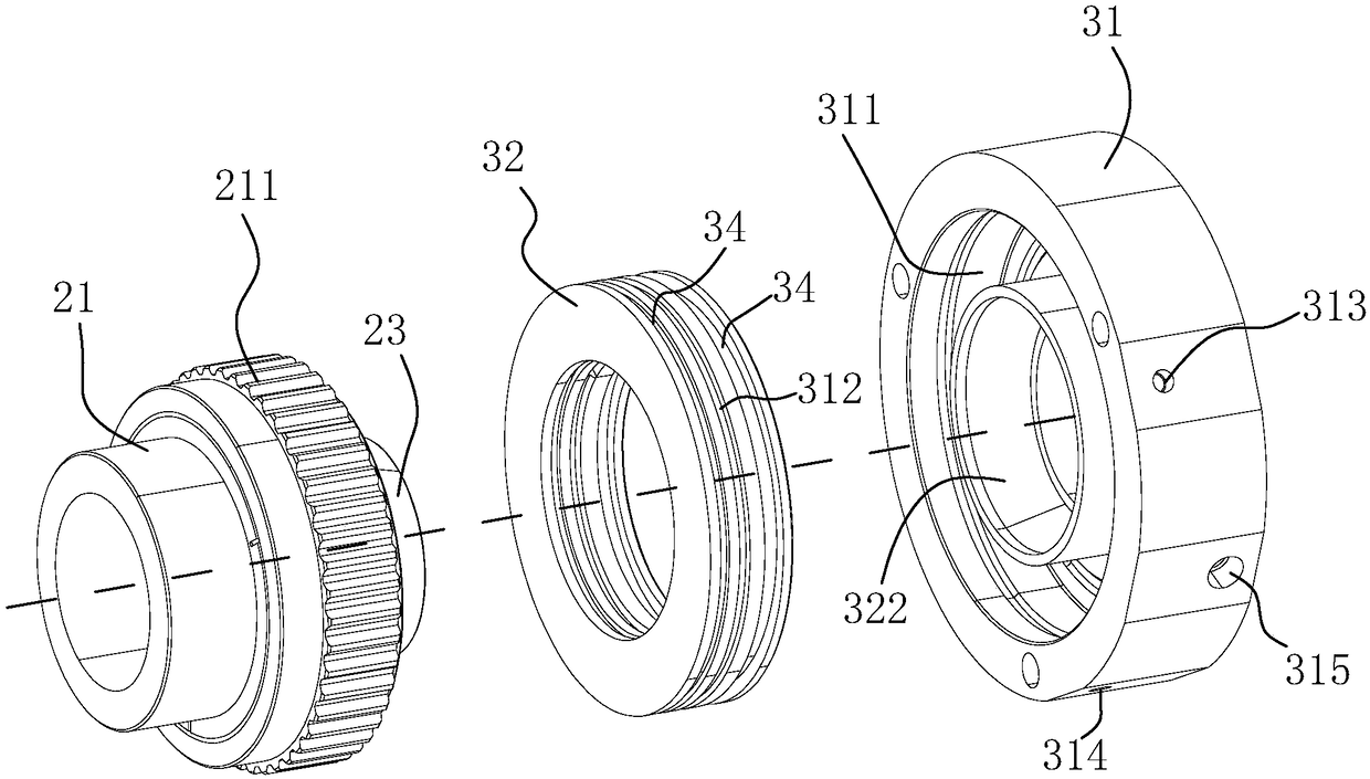
[0047] Refer to the attached Figure 7 , On the basis of the first embodiment, the difference from the first embodiment is that the radial cross-sections of the piston 32 and the cylinder block 31 are both stepped, so that the stepped fingers are formed, and the piston 32 has a An extension of the inner wall, and the cylinder block 31 covers the outer circumferential surface of the piston 32 . An annular groove 34 is provided on the inner side wall of the oil cylinder block 31 and the outer side wall of the piston 32 , and a sealing ring is installed in the annular groove 34 . In this embodiment, the annular groove 34 may be provided with two places on the piston 32 and the oil cylinder block 31, and the two places can also be installed with a high-pressure sealing ring 35 and a low-pressure sealing ring 36 respectively. The modified structure can achieve a better sealing effect, and the leakage groove 312 can be omitted.

Embodiment 3

[0049] An injection molding machine, comprising the connecting rod clamping mechanism as in all the above-mentioned embodiments.


PUM


Abstract

The invention discloses a connecting rod clamping mechanism and solves the problems of high wear of five-fulcrum connecting rods, arrangement positions of oil cylinder assemblies, high probability offires in high-temperature regions and inconvenience in maintenance. The connecting rod clamping mechanism comprises a moving mold plate, a fixed mold plate and a base plate, wherein the moving mold plate is connected with the base plate through a mold plate hinge assembly, the connecting rod clamping mechanism also comprises a threaded mold adjusting assembly arranged on the outer side of the baseplate, a mode locking oil cylinder assembly and a mode locking pull rod, the mode locking oil cylinder assembly is arranged on the same side of the base plate; one end of the mode locking pull rod penetrates the moving mold plate and the base plate and is matched with the mode locking oil cylinder assembly and the threaded mold adjusting assembly on the outer side of the base plate respectively,and the other end of the mode locking pull rod penetrates the fixed mold plate; a drive part is also arranged on the base plate and connected with the mold plate hinge assembly. The connecting rod clamping mechanism is good in mode locking accuracy, high in efficiency and convenient to maintain and cannot cause safety accidents easily.

Description

technical field [0001] The invention relates to the field of injection molding machinery, more specifically, to a link mold clamping mechanism and an injection molding machine thereof. Background technique [0002] The traditional hinged link mold clamping mechanism relies on the amplification of the force generated by the straightening of the hinge to obtain the clamping force. The magnitude of this clamping force is difficult to control, and it is also difficult to accurately set the clamping force as required. The mold clamping force and demoulding force are generated by the amplification of the cylinder force. The larger the cylinder force required, the larger the diameter of the cylinder. When doing fast mold movement, more power hydraulic oil is required to participate, resulting in high energy consumption; due to various The accumulation of processing tolerances of the hinges and templates makes the parallelism between the templates clamping the mold not high, resulti...

Claims


Application Information

Patent Timeline
IPC IPC(8): B29C45/68
CPCB29C45/681
Inventor 戎国荣
Owner 宁波云上塑料机械有限公司
Why Eureka
Try Eureka