Rail transit vehicle wheel rim parameter online dynamic measuring device and method
A dynamic measurement, rail transit technology, applied in the field of rail transit, to achieve the effects of improved detection accuracy, fast detection efficiency, and high detection accuracy
- Summary
- Abstract
- Description
- Claims
- Application Information
AI Technical Summary
Problems solved by technology
Method used
Image
Examples
Embodiment 1
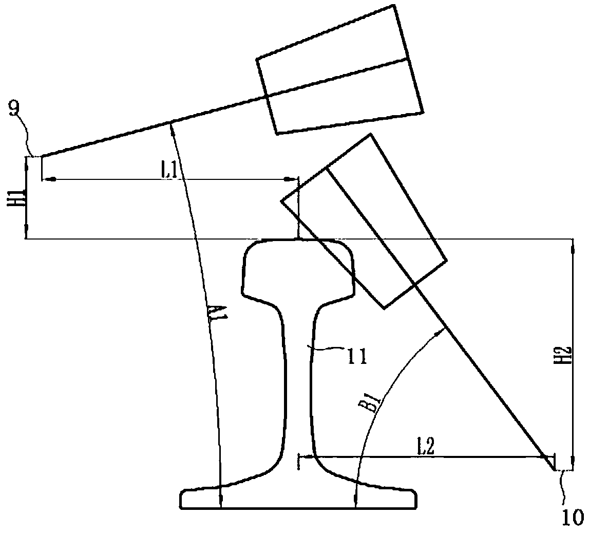
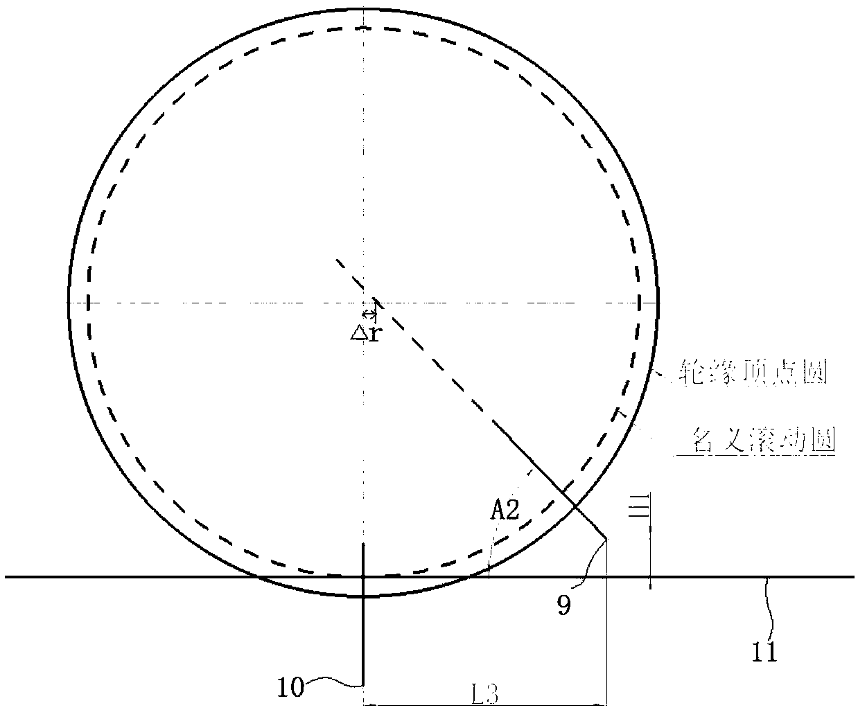
[0068] combine figure 2 , image 3 , a kind of on-line dynamic measuring device of rail transit wheel rim parameter of the present embodiment, comprises the outside laser displacement sensor 9 that is installed on the outside of track 11 and the inside laser displacement sensor 10 that is installed on the inside of track 11, and these two laser displacement sensors are It is a two-dimensional laser displacement sensor, wherein the outer laser displacement sensor 9 is used to collect the contour line from the apex of the wheel rim to the nominal rolling circle of the wheel, and the height of the sensor head above the top surface of the track 11 is H 1 , the horizontal distance from the center of the rail top is L 1 , the angle between the probe beam and the direction perpendicular to the track is A 1 , the angle between it and the direction parallel to the track is A 2 ; The inner laser displacement sensor 10 is used to collect the contour line from the inner rim surface of...
Embodiment 2
[0071] A kind of on-line dynamic measuring device of rail transit wheel rim parameter of this embodiment, its structure is the same as embodiment 1, further, two rails 11 are all symmetrically installed with described outer laser displacement sensor 9 and inner laser displacement sensor 10 , so that the rim parameters of the wheels on both sides can be measured separately.
Embodiment 3
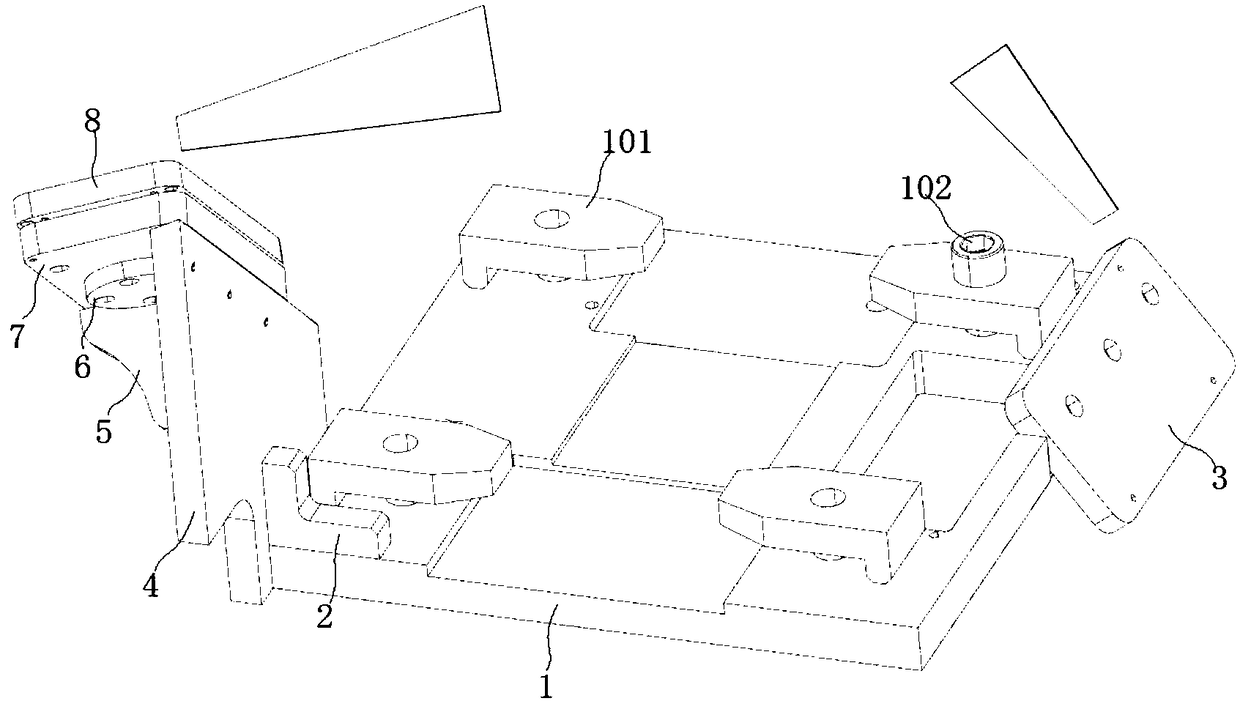
[0073] The on-line dynamic measuring device of a kind of rail transit wheel rim parameter of this embodiment, its structure is basically the same as embodiment 2, and its difference mainly lies in: the outer laser displacement sensor 9 and the inner laser displacement sensor 10 described in this embodiment all pass the sensor Mounting mechanism for installation, such as figure 1 As shown, the sensor installation mechanism includes a base plate 1, an inner mounting plate 3 and an outer mounting plate 8, wherein the base plate 1 is fixedly installed on the bottom of the track 11, the inner mounting plate 3 and the outer mounting plate 8 are fixedly connected with the base plate 1, and the inner mounting plate The installation angles of the plate 3 and the outer mounting plate 8 correspond to the installation angles of the inner laser displacement sensor 10 and the outer laser displacement sensor 9 respectively. On the bottom plate 1 of the present embodiment, a briquetting block...
PUM
 Abstract
Description
Claims
Application Information
 - R&D
- Intellectual Property
- Life Sciences
- Materials
- Tech Scout
- Unparalleled Data Quality
- Higher Quality Content
- 60% Fewer Hallucinations
Browse by: Latest US Patents, China's latest patents, Technical Efficacy Thesaurus, Application Domain, Technology Topic, Popular Technical Reports.
© 2025 PatSnap. All rights reserved.Legal|Privacy policy|Modern Slavery Act Transparency Statement|Sitemap|About US| Contact US: help@patsnap.com


