Chain wear test device and chain wear test method
A wear test and chain technology, applied in measuring devices, testing wear resistance, instruments, etc., can solve problems such as increased energy consumption and complex structure
Pending Publication Date: 2019-02-26
SUZHOU UNIVERSAL GRP TECH CO LTD
View PDF0 Cites 2 Cited by
- Summary
- Abstract
- Description
- Claims
- Application Information
AI Technical Summary
Problems solved by technology
[0003] The purpose of this application is to provide a chain wear test device and chain wear test method, to solve the existing in the prior art by applying reverse torque to two sprockets in each set of sprockets of t
Method used
View moreImage
Smart ImageViewing Examples
Examples
 PUM
 Abstract
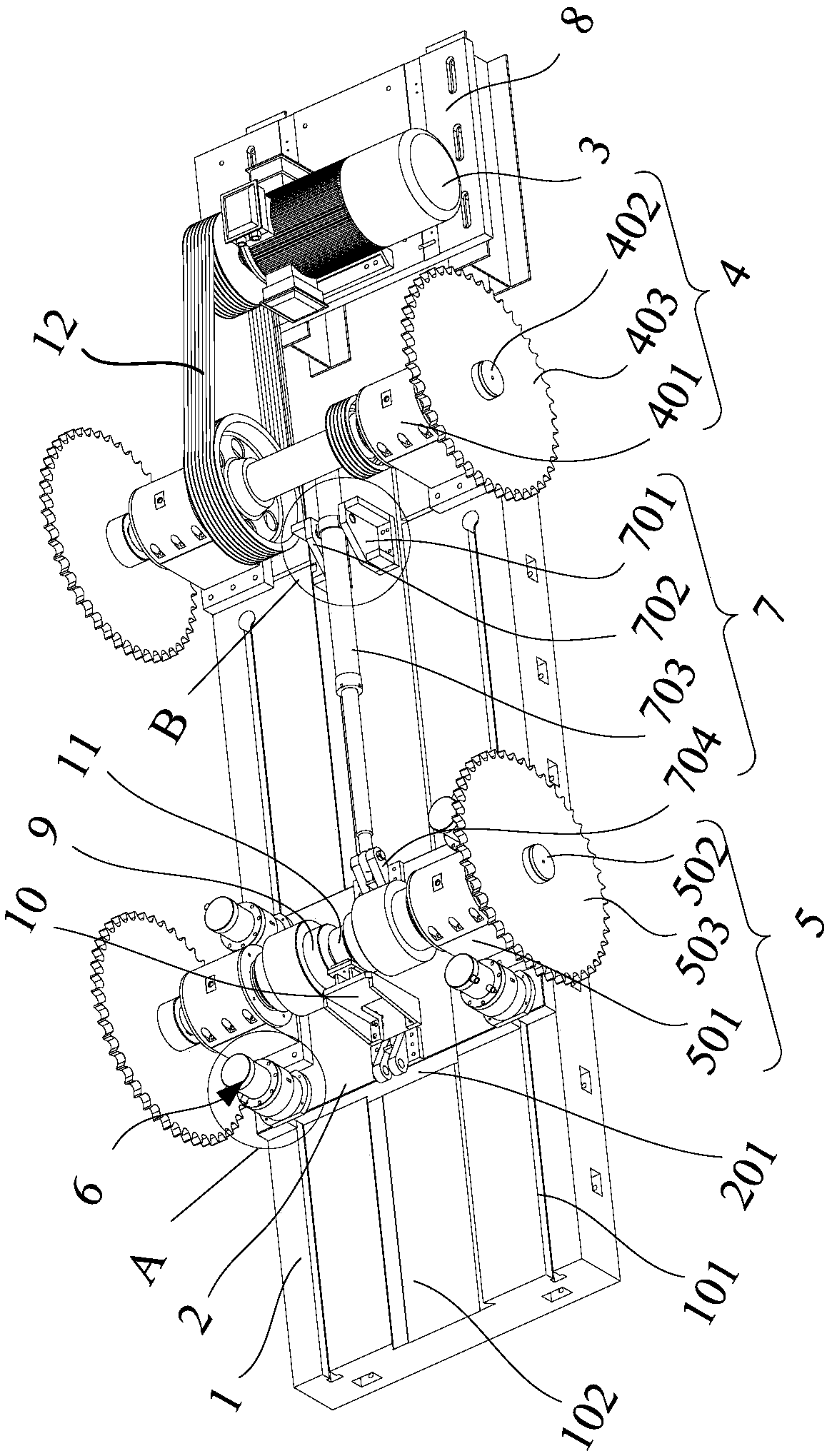
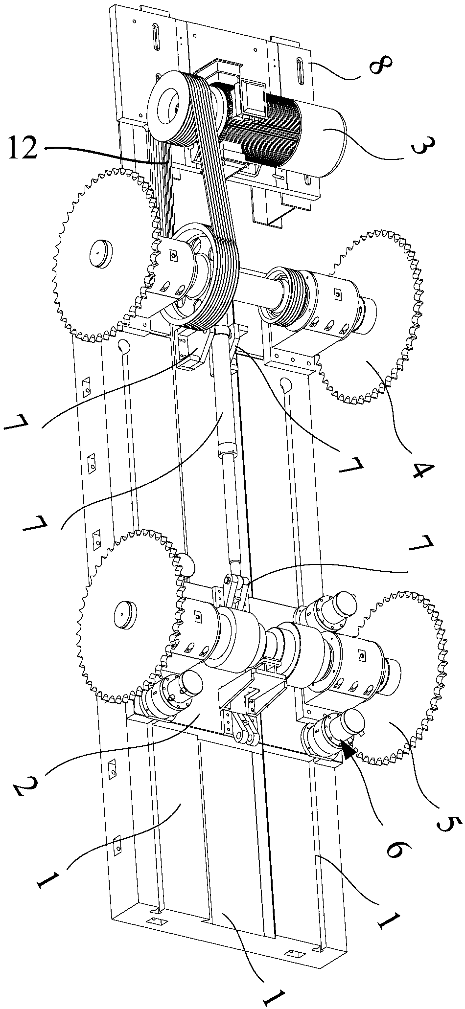
Theapplication relates to the technical field of chain wear test, in particular to a chain wear test device and a chain wear test method. The chain wear test device comprises a fixed plate, a movableplate, a driving device, a driving sprocket mechanism, a driven sprocket mechanism, a fixing component and a tensioning component; a first bearing block of the driving sprocket mechanism is arranged on the fixed plate; a driving shaft of the driving sprocket mechanism is inserted in the first bearing block, two ends of the driving shaft are sleeved with first sprockets, and the projections of thetwo first sprockets in a direction perpendicular to the axis of the driving shaft coincide with each other; the driving device drives the driving shaft to rotate; the movable plate can slide relativeto the fixed plate; the tensioning assembly is used for adjusting the distance between the movable plate and the fixed plate; the fixing component is used for fixing the movable plate to the fixed plate; and the driven sprocket mechanism comprises a second bearing block, a driven shaft and a second sprocket. The test device can simulate the real operation of a chain, and achieves the purpose of applying a large torque to the chain while saving energy.
Description
technical field [0001] The present application relates to the technical field of chain wear test, in particular to a chain wear test device and a chain wear test method. Background technique [0002] At present, the chain wear test bench is used to test the elongation of the chain under test conditions and within a certain time range. The existing chain wear tester applies reverse torque to the two sprockets in each set of sprockets, so that a part of the chain hanging on each set of sprockets is in a tensioned state, and the other part is in a loose state, and then Simulate the actual operation of the chain, but add a hydraulic torque loading system, the structure is complicated, and the energy consumption is increased. Contents of the invention [0003] The purpose of this application is to provide a chain wear test device and chain wear test method, to solve the existing in the prior art by applying reverse torque to two sprockets in each set of sprockets of the chain ...
Claims
Login to View More Application Information
Patent Timeline
 IPC IPC(8): G01N3/56
CPCG01N3/56G01N2203/0282
Inventor 黄伟达刘家强黄千益胡清
Owner SUZHOU UNIVERSAL GRP TECH CO LTD
Features
- R&D
- Intellectual Property
- Life Sciences
- Materials
- Tech Scout
- Unparalleled Data Quality
- Higher Quality Content
- 60% Fewer Hallucinations
Learn More Browse by: Latest US Patents, China's latest patents, Technical Efficacy Thesaurus, Application Domain, Technology Topic, Popular Technical Reports.
© 2025 PatSnap. All rights reserved.Legal|Privacy policy|Modern Slavery Act Transparency Statement|Sitemap|About US| Contact US: help@patsnap.com


