Carbonate rock surface fracture reservoir body characterization method

A carbonate rock, fracture-cavity storage technology, applied in complex mathematical operations, seismic signal processing, seismology for logging records, etc. Collectively describe problems such as leakage to achieve the effect of improving the coincidence rate and improving the recovery rate

Active Publication Date: 2019-02-26
CHINA PETROLEUM & CHEM CORP +1
View PDF5 Cites 3 Cited by
  • Summary
  • Abstract
  • Description
  • Claims
  • Application Information

AI Technical Summary

Problems solved by technology

[0009] What the present invention aims to solve is the problem that the existing methods for describing fractured-vuggy reservoirs on the surface of carbonate rocks have the problem of the leakage of the description of surface reservoirs and the inability to accurately reflect the spatial distribution of surface fractured-vuggy bodies

Method used


Image

  • Carbonate rock surface fracture reservoir body characterization method
  • Carbonate rock surface fracture reservoir body characterization method
  • Carbonate rock surface fracture reservoir body characterization method

Examples


Embodiment 1

[0051] In order to solve the above-mentioned technical problems existing in the prior art, an embodiment of the present invention provides a method for characterizing fracture-vug reservoirs on the surface of carbonate rocks.

[0052] figure 1 A flow chart of the method for characterizing fractured-vuggy reservoirs on the surface of carbonate rocks according to Embodiment 1 of the present invention is shown.

[0053] refer to figure 1 In this embodiment, the fracture-vuggy reservoir description method on the surface of carbonate rocks includes:

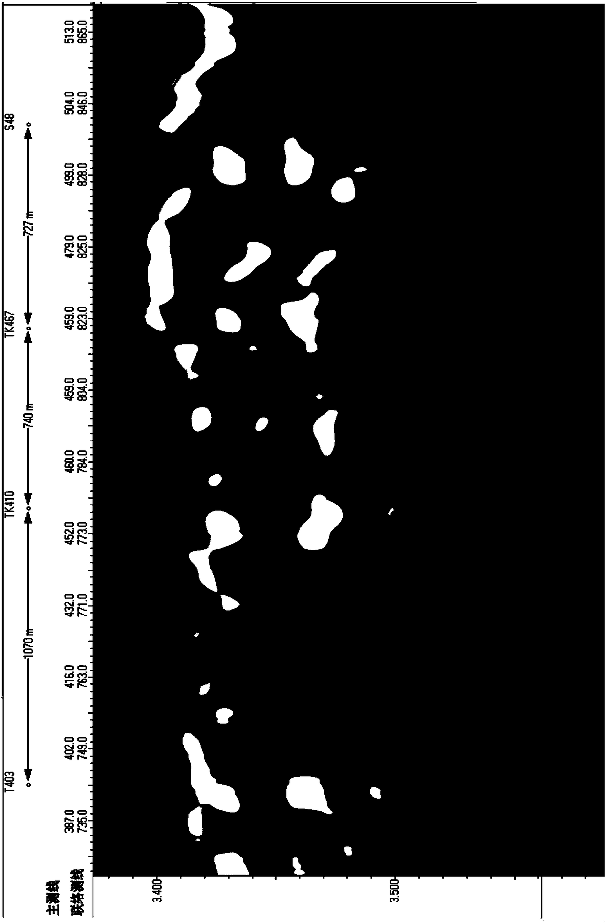
[0054] Step S1: Calculate the root mean square amplitude attribute in the first depth range of the carbonate rock surface.

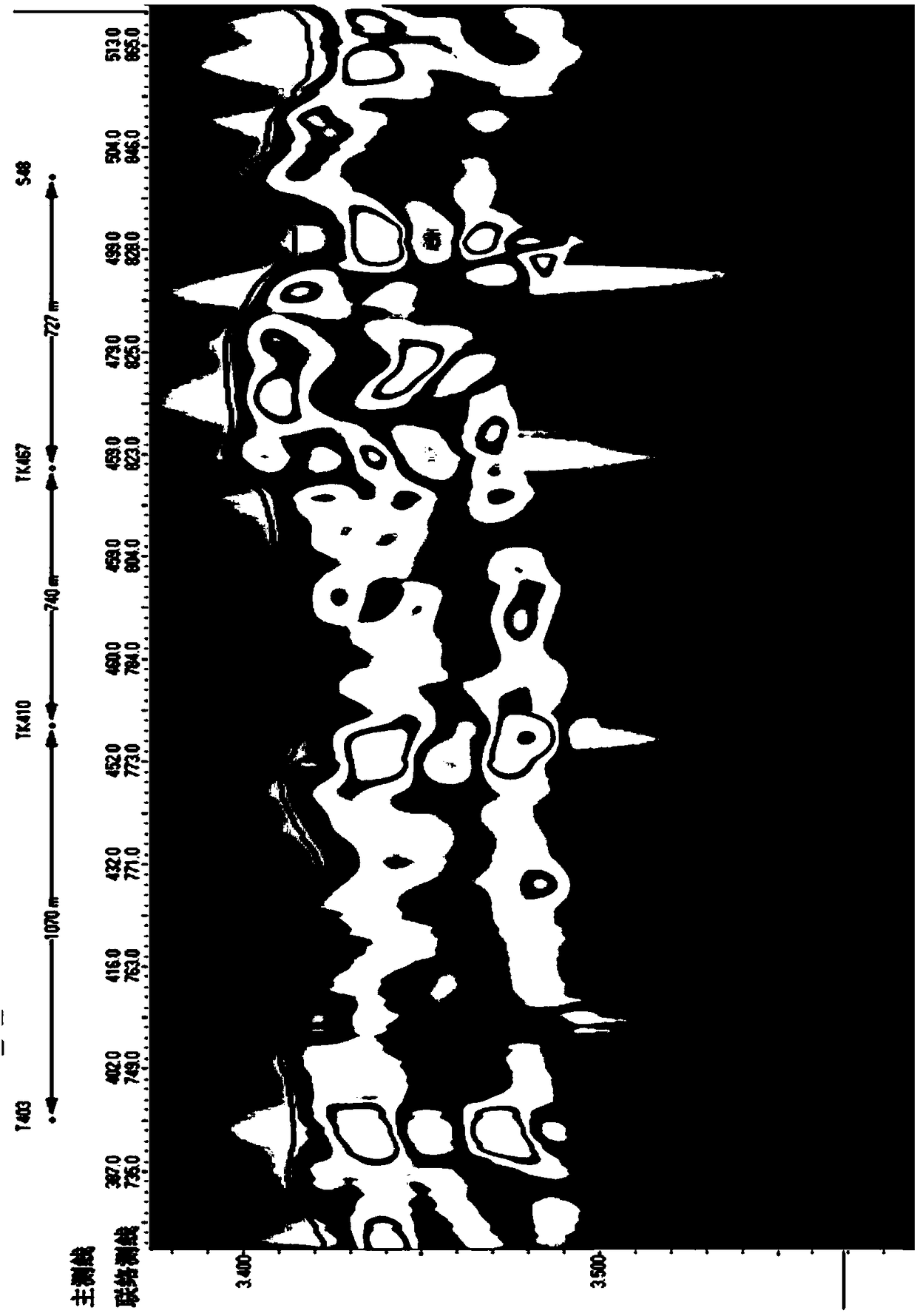
[0055] Step S2: Calculate the relative wave impedance property in the second depth range of the carbonate rock surface.

[0056] Step S3: Establish a regression function between the root mean square amplitude attribute and the relative wave impedance attribute.

[0057] Specifically, through the above-mentio...

Embodiment 2

[0066] In this embodiment, on the basis of the first embodiment, steps S1-S3 and S5 are further limited, and step S4 is further defined differently from the first embodiment.

[0067] In this embodiment, the method for describing fractured-vuggy reservoirs on the surface of carbonate rocks includes:

[0068] Step S1 : Calculating the root mean square amplitude attribute in the first depth range of the carbonate rock surface.

[0069] Specifically, according to the original seismic data volume in the first depth range of the carbonate rock surface layer, the root mean square amplitude value in the first depth range of the carbonate rock surface layer is obtained; the obtained root mean square amplitude value is reciprocated , and the reciprocal of the root mean square amplitude value is homogenized to obtain the root mean square amplitude attribute in the first depth range of the carbonate rock surface. Among them, the calculation of the root mean square amplitude value is: sq...


PUM


Abstract

The invention discloses a carbonate rock surface fracture reservoir body characterization method. The method comprises the steps: calculating a root mean square amplitude property in a first depth range of the carbonate rock surface and calculating a relative wave impedance property in a second depth range; establishing a regression function according to the calculated two properties, converting one attribute into the other attribute according to the regression function, depicting a fracture reservoir body according to the values of the converted and unconverted attributes to obtain two piecesof fracture reservoir body data, and performing the coupling of the fracture reservoir body data to obtain a coupled data body of the carbonate rock surface fracture reservoir body. The method solvesthe problem of characterization loss caused by using the root mean square amplitude attribute to characterize the surface layer of a carbonate rock, improves the coincidence rate between a characterization result and actual drilling, and provides reliable basis for the potential tapping of the residual oil and improving the recovery of the fracture-cavity type reservoir.

Description

technical field [0001] The invention relates to the technical field of petroleum exploration seismic reservoir prediction, in particular to a method for describing fractured-vug reservoirs on the surface of carbonate rocks. Background technique [0002] The surface layer refers to the unconformity surface of carbonate formation (T 7 4 ) within the range of 0-60 meters below the formation. Fractures and caves are the main storage space for oil and gas in the Tahe carbonate formation, and the surface fractures and caves are the main production intervals of Ordovician oil and gas. Therefore, the characterization of surface fractures and caves plays an important role in improving the success rate of drilling and oil recovery. important meaning. [0003] The fractured-vuggy reservoirs in the Ordovician strata mainly show strong reflections in the shape of "beads", while the surface fractured-vuggy bodies are due to the distance T 7 4 The weathering crust interface is relativ...

Claims


Application Information

Patent Timeline
Patent Type & Authority Applications(China)
IPC IPC(8): G01V1/30G01V1/50G06F17/18
CPCG01V1/30G01V1/50G06F17/18
Inventor 刘坤岩邬兴威司朝年韩东解丽慧王萍
Owner CHINA PETROLEUM & CHEM CORP
Why Eureka
Try Eureka