Image capture apparatus

A shading pattern and sensor technology, applied in optics, instruments, characters and pattern recognition, etc., can solve the problems of limited light input of the sensor, easy scattered transmission of light beams, and poor image quality, etc. Improve, improve the crosstalk problem, improve the effect of crosstalk

Active Publication Date: 2019-02-26
GINGY TECH
View PDF8 Cites 11 Cited by
  • Summary
  • Abstract
  • Description
  • Claims
  • Application Information

AI Technical Summary

Problems solved by technology

During the image capturing process of the sensor, the light beam reflected by the fingerprint is easily scattered to the sensor, resulting in poor image quality and affecting the recognition result
Although the existing technology improves the image quality, the current technology tends to limit the light input of the sensor excessively while improving the crosstalk.

Method used


Image

  • Image capture apparatus
  • Image capture apparatus
  • Image capture apparatus

Examples


Embodiment Construction

[0043] In the following detailed description of each embodiment with reference to the accompanying drawings, the foregoing and other technical contents, features and effects related to the present invention will be clearly presented. The directional terms mentioned in the following embodiments, such as "upper", "lower", "front", "rear", "left", "right", etc., are only the directions with reference to the drawings. Therefore, the directional terms used are for illustration, but not for limiting the present invention. In addition, in any of the following embodiments, the same or similar elements will use the same or similar reference numerals.

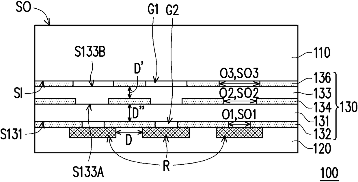
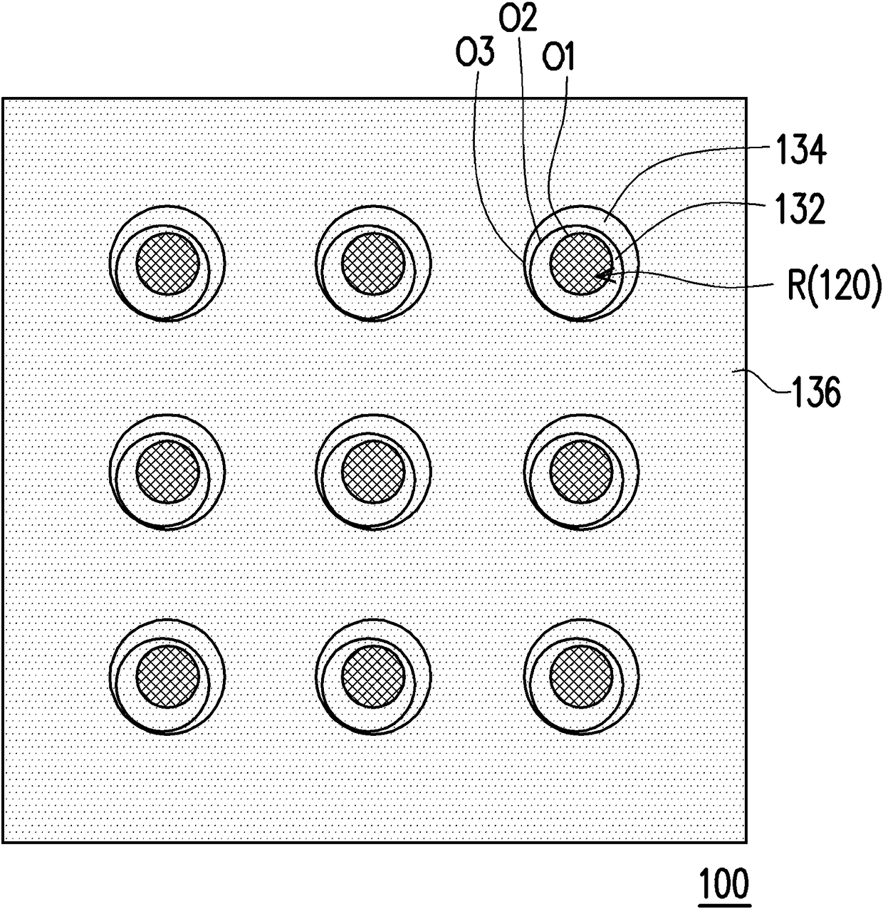
[0044] figure 1 It is a schematic cross-sectional view of the imaging device of the first embodiment of the present invention. figure 2 and image 3 Respectively, they are schematic top views of the image capturing device according to the first embodiment of the present invention when there is no manufacturing tolerance and when there is a...


PUM


Abstract

An image capture apparatus includes a cover plate, a sensor, and an optical collimator. The optical collimator is disposed between the cover plate and the sensor and includes a first light shielding pattern layer, a second light shielding pattern layer, and a third light shielding pattern layer that overlap each other. The first, second, and third light shielding pattern layers respectively have aplurality of first, second, and third light transmission openings. The size of each of the third light transmission openings is greater than or equal to the size of each of the second light transmission openings, and the size of each of the second light transmission openings is larger than the size of each of the first light transmission openings. Alternatively, the size of each of the third light transmission openings is larger than the size of each of the second light transmission openings, and the size of each of the second light transmission openings is greater than or equal to the size of each of the first light transmission openings.

Description

Technical field [0001] The present invention relates to a photoelectric device, and in particular to an imaging device. Background technique [0002] The types of biometric recognition include face, voice, iris, retina, vein, palm print and fingerprint recognition. According to different sensing methods, biometric identification devices can be divided into optical, capacitive, ultrasonic and thermal induction types. Generally speaking, an optical biometric identification device includes a light source, a light guide element, and a sensor. The light beam emitted by the light source illuminates the object to be identified pressed on the light guide element. The sensor receives the light beam reflected by the object to be identified to perform biometric identification. During the image capturing process of the sensor, the light beams reflected by the fingerprint are easily transmitted to the sensor in a scattered manner, resulting in poor image capturing quality and affecting the...

Claims


Application Information

Patent Timeline
Patent Type & Authority Applications(China)
IPC IPC(8): G06K9/20G02B27/30
CPCG02B27/30G06V10/147
Inventor 钟炜竣巫仁杰
Owner GINGY TECH
Why Eureka
Try Eureka