
Optimized control method for comprehensive energy system

An integrated energy system and optimized control technology, applied in wind power generation, single-network parallel feeding arrangement, photovoltaic power generation, etc., can solve the problems of distributed energy, flexible load optimization management, lack of distributed power supply and flexible load modeling To achieve the effect of realizing multi-energy complementary collaborative optimization control, ensuring the consistency of data interaction, and realizing energy collaborative optimization

Active Publication Date: 2019-02-26
YUNNAN POWER GRID CO LTD ELECTRIC POWER RES INST
View PDF3 Cites 15 Cited by
  • Summary
  • Abstract
  • Description
  • Claims
  • Application Information

AI Technical Summary

Problems solved by technology

[0004] This application provides an optimized control method for an integrated energy system to solve the problem of public information models in the prior art. Although most of the information models involved in power automation are formulated, there is a lack of modeling of distributed power sources and flexible loads. Unable to meet the needs of distributed energy and flexible load optimization management

Method used


Image

  • Optimized control method for comprehensive energy system
  • Optimized control method for comprehensive energy system
  • Optimized control method for comprehensive energy system

Examples


Embodiment Construction

[0027] The technical solutions in the embodiments of the present invention will be clearly and completely described below in conjunction with the accompanying drawings in the embodiments of the present invention. Obviously, the described embodiments are only some, not all, embodiments of the present invention. Based on the embodiments of the present invention, all other embodiments obtained by persons of ordinary skill in the art without creative efforts fall within the protection scope of the present invention.

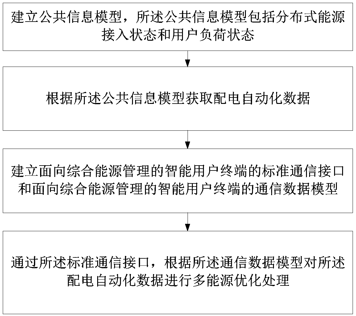
[0028] see figure 1 , is a flowchart of an optimal control method for an integrated energy system provided by an embodiment of the present invention. The method comprises the steps of:

[0029] Establish a public information model, the public information model includes distributed energy access status and user load status;

[0030] Acquiring distribution automation data according to the public information model;

[0031] Establish a standard communication interfac...


PUM


Abstract

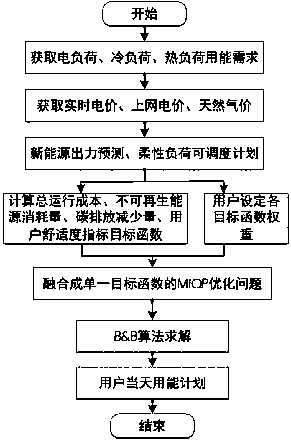
The invention discloses an optimized control method for a comprehensive energy system. The method comprises the following steps: establishing a public information model, acquiring distribution automation data, establishing a standard communication interface and a communication data model, and performing multi-energy optimization processing on the distribution automation data according to the communication data model through a standard communication interface. In the optimized control method for a comprehensive energy system, firstly, user-side distributed energy is integrated with a comprehensive energy system, contributing to multi-energy complementary collaborative optimization control implementation, and data interaction consistency among different systems is ensured in the comprehensive energy system. The standard communication interface of an intelligent user terminal facing comprehensive energy management, and a communication data model are established for realizing horizontal multi-energy complementation and vertical demand response joint optimization in the comprehensive energy system, and energy collaborative optimization is realized from two aspects of a source end and aload end. The method can perform best match on energy supply and energy consumption in a user-side comprehensive energy system, and can satisfy needs of distributed energy and flexible load optimization management.

Description

technical field [0001] The invention relates to the technical field of energy system control, in particular to an optimal control method for an integrated energy system. Background technique [0002] Facing the increasingly severe energy situation and the promotion of new energy policies vigorously advocated by the state, related technical research and engineering demonstration of integrated energy management have been put on the agenda. In the future multi-party interactive energy trading mode and multi-energy complementary operation network conditions, fully tap the flexible load and distributed energy dispatch potential in the integrated energy system, whether it is for distributed energy consumption, power grid peak-shaving and valley filling, or Participation in the provision of ancillary services is important. [0003] The integrated energy system integrates different types of energy such as electricity, heat, cold, and gas. The control of the integrated energy system...

Claims


Application Information

Patent Timeline
Patent Type & Authority Applications(China)
IPC IPC(8): H02J3/46H02J3/00H02J3/38
CPCH02J3/383H02J3/386H02J3/00H02J3/46H02J2203/20Y02E10/56Y02E10/76
Inventor 邹京希李维曹敏王洪林王科聂鼎
Owner YUNNAN POWER GRID CO LTD ELECTRIC POWER RES INST
Learn More