Filter device

A filter and support part technology, applied in the field of filter devices, can solve the problem of not having to take out, and achieve the effects of alleviating pain and reducing secondary operations

Pending Publication Date: 2019-03-01
SHANGHAI BLUEVASCULAR MEDTECH CO LTD
View PDF0 Cites 2 Cited by
  • Summary
  • Abstract
  • Description
  • Claims
  • Application Information

AI Technical Summary

Problems solved by technology

[0006] However, once a partially degradable filter is implanted in the patient, it is impossible to remove it from the body. Although this type of filter can be converted into a stent, which can reduce the incidence of long-term complications of the filter, the filter exists as a metal foreign body in the blood vessel for a long time. , there is bound to be a certain potential risk

Method used


Image

  • Filter device
  • Filter device
  • Filter device

Examples


Embodiment 1

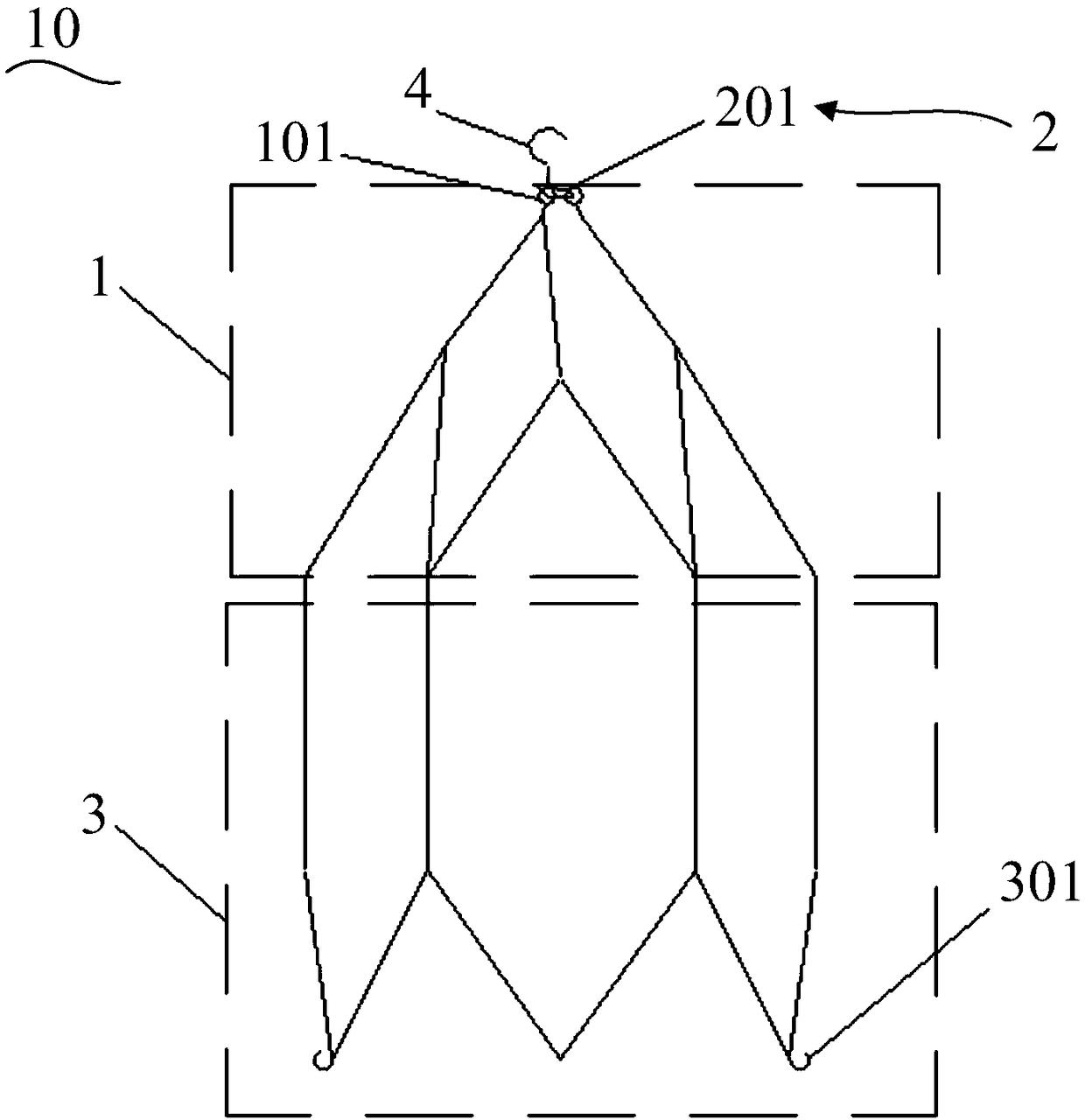
[0048] figure 1 It is a structural schematic diagram of the filter device of Embodiment 1 of the present invention, such as figure 1 As shown, the filter device 10 includes a filtering part 1 , a constraining part 2 , a supporting part 3 and a connecting part 4 . The filter part 1 has opposite first and second ends, and the filter device 10 has opposite head and tail ends, the first end corresponds to the head end and is usually the end close to the heart, i.e. proximal end. The supporting part 3 is used as a support part in this embodiment, and has opposite first and second ends.

[0049] The constraining part 2 is made of biodegradable material, constrained to the first end of the filter part 1, so that the first end of the filter part 1 is closed to capture thrombus. The second end of the filtering part 1 is connected to the first end of the supporting part 3 . The filter part 1 is formed into a filter mesh structure under the constraints of the constraint part 2, and t...

Embodiment 2

[0074] The filter device 20 provided in this embodiment is basically the same as that in Embodiment 1, and only the differences will be described below.

[0075] Figure 6 It is a structural schematic diagram of the filter device of Embodiment 2 of the present invention, such as Figure 6As shown, the filter device 20 includes a filtering part 1 , a restricting part 2 , a supporting part 3 and a connecting part 4 , and also includes a recovery part 5 . The support part 3 and the recovery part 5 together constitute the support part of the present invention. The frame portion has opposite first and second ends, and the second end of the frame portion corresponds to the rear end of the filter device 20 .

[0076] In this embodiment, the whole length of the support part 3 does not overlap with the filter part 1 in the axial direction of the filter device 20 . Specifically, one end of the support part 3 is connected to the second end of the filter part 1, and the other end of th...

Embodiment 3

[0087] The filter device provided in this embodiment is basically the same as that in Embodiment 2, and only the differences will be described below.

[0088] Figure 10 It is a structural schematic diagram of the filter device of the third embodiment of the present invention, such as Figure 10 As shown, the filter device 30 includes a filtering part 1 , a restricting part 2 , a supporting part 3 , a connecting part 4 and a recovery part 5 .

[0089] Wherein, there are two connecting parts 4, one is arranged at the head end of the filter device 30, and the other is arranged at the tail end of the filter device 20, at this moment, the filter device can be recovered through the connecting part 4 positioned at the head end of the filter device 30 30, and the filter device 20 can be recovered through another connection part 4 located at the tail end of the filter device 30. Here, the connection method between the connection part 4 of this embodiment and the head end and the tail...


PUM


Abstract

The invention provides a filter device. The filter device comprises a filtering part, a constraint part, a bracket part and a connecting part, wherein the filtering part is provided with a first end and a second end opposite to each other, the constraint part can degrade and is at least used for restraining the first end of the filtering part, the bracket part is provided with a first end and a second end opposite to each other, the first end of the bracket part is connected with the second end of the filtering part and the bracket part is arranged coaxial to the filtering part, the connectingpart is arranged on one or more of the first end of the filtering part and the second end of the bracket part and is used for connecting with an external mechanism, and the constraint part is furtherused for restraining the second end of the bracket part when the connecting part is arranged at the second end of the bracket part. The filter device can be taken out from the body and also can realize partial degrading in the body, therefore, the occurrence rate of long-term complications is reduced, and meanwhile, secondary surgery also can be reduced.

Description

technical field [0001] The invention relates to the technical field of medical instruments, in particular to a filter device. Background technique [0002] Venous Thromboembolism (VTE) is a common clinical disease with high morbidity and mortality. VTE includes deep vein thrombosis (Deep Vein Thrombosis, referred to as DVT) and pulmonary embolism (Pulmonary Embolism, referred to as PE). DVT often occurs in the veins of the lower extremities, while PE is mainly caused by the thrombosis in the venous system or right heart, which falls off and enters the pulmonary artery, and is the main cause of morbidity and death. [0003] Anticoagulant therapy has always been the gold standard in VTE treatment, with the aim of preventing thrombosis, preventing PE and restoring the patency of embolized veins. When anticoagulation is contraindicated or anticoagulation has to be terminated due to bleeding complications, the implantation of a Vena Cava Filter (VCF) can effectively intercept t...

Claims


Application Information

Patent Timeline
Patent Type & Authority Applications(China)
IPC IPC(8): A61F2/01
CPCA61F2002/016A61F2/86A61F2/011A61F2/0108A61F2/0105A61F2210/0004A61F2002/9528A61F2220/0016A61F2250/0059A61F2230/005A61F2230/0054A61F2/04A61F2002/018A61F2310/00365
Inventor 朱永锋朱清李中华张琳琳缴文会韩建超高延彬
Owner SHANGHAI BLUEVASCULAR MEDTECH CO LTD
Why Eureka
Try Eureka