handlebars

A handlebar and handlebar technology, applied in the handlebar field, can solve the problems of operator inconvenience, unfavorable expansion of handlebars, limited space, etc., and achieve flexible and diverse cross-sectional shapes, which are beneficial to production and maintenance, and are convenient to open and fasten. Effect

Active Publication Date: 2021-01-05
台州市展翔科技有限公司
View PDF1 Cites 0 Cited by
  • Summary
  • Abstract
  • Description
  • Claims
  • Application Information

AI Technical Summary

Problems solved by technology

[0004] 1. The handle cover is tightly attached to the handle steel pipe, and it cannot be easily or even impossible to remove or install the handle cover. Most of the damaged handle covers on the road are of this type; 2. The handle cover The friction between the handlebar steel pipe and the handlebar is insufficient, so that the handlebar cover can rotate in the circumferential direction, especially when the temperature is high in summer, most of the handlebar cover will have such a phenomenon, such a handlebar cover is easy to fall off, which brings inconvenience to the operator and even cause safety hazard
[0005] The device for fixing the handle cover in the prior art is not easy to disassemble. For example, the patent No. 200820170730.6 discloses the technical solution of the utility model patent of the handle cover of the tubular nesting structure. Regardless of assembly or disassembly, the tubular nesting structure needs to be The handlebars are removed from the car as a whole to expose the port at the front end of the fuel pipe 1, and then related operations can be performed, which is very troublesome; as the vehicle develops in a multi-functional direction, it is necessary to make full use of various precious spaces on the vehicle, and the car The handle is used as the holding device of the vehicle. It is the main development trend to install various devices in the metal tube of the handlebar. In the prior art, for example, 200820170730.6, the scheme of the sleeve of the tubular nesting structure is to arrange an annular connecting plate at the tail port of the filling pipe 1, which undoubtedly increases the manufacturing process of the filling pipe 1, and is also equivalent to the A barrier is set at the position, which is inconvenient to disassemble and assemble the device arranged in the filling pipe 1, and the existing technology is not conducive to expanding the function of the handlebar

Method used


Image

  • handlebars
  • handlebars
  • handlebars

Examples


Embodiment Construction

[0027] The technical solution of the handlebar of the present invention will be further described in detail below in conjunction with the embodiments shown in the accompanying drawings.

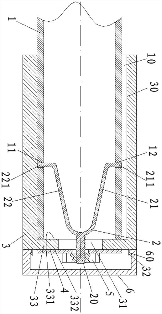
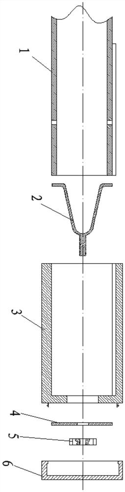
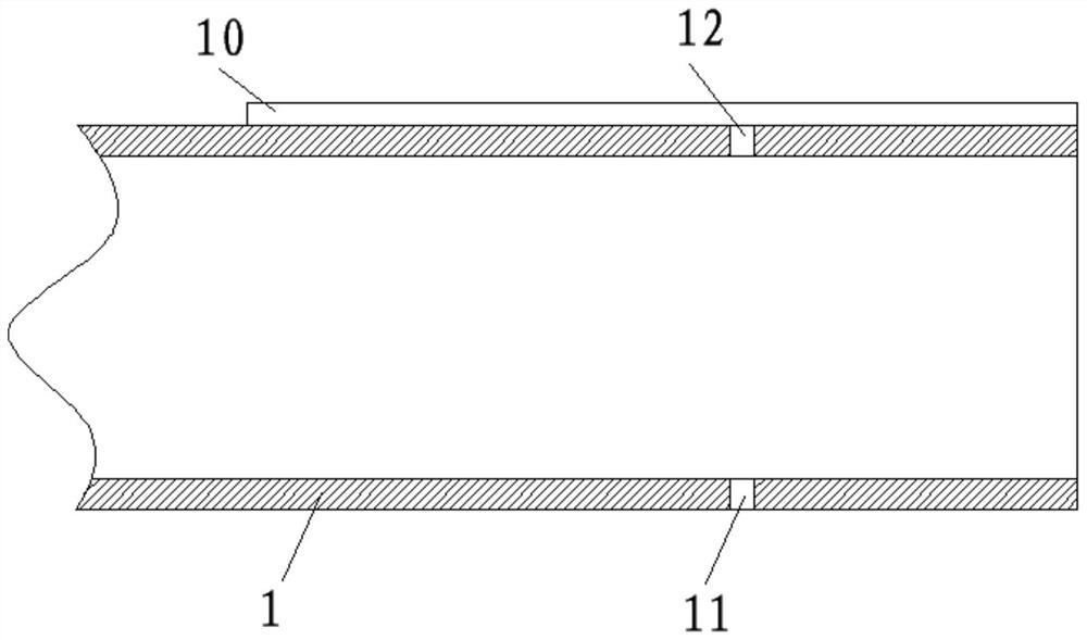
[0028] as attached figure 1 to attach Figure 8 As shown, a handlebar includes a handlebar metal pipe 1 and a handle cover 3, the handle cover 3 includes a first port 34 and a second port 35, and the handle cover 3 is sleeved on the vehicle through its first port 34. On the outer wall of the metal pipe 1, the handle cover 3 is the part that the operator holds with his hands, and the first through hole 11 and the second through hole 12 are set on the pipe wall of the handlebar metal pipe 1. A Y-shaped connector 2 is arranged in the metal pipe 1, and the Y-shaped connector 2 forms a curved depression in the metal pipe 1 of the handlebar. The Y-shaped connector 2 includes a bolt 20, a first connecting arm 21 and a second The connecting arm 22 extends a first connecting arm 21 and a second conn...


PUM


Abstract

The invention relates to a handlebar, which comprises a handlebar metal tube. A handle outer sleeve sleeves the handlebar metal tube; a Y-shaped connecting piece is arranged in the handlebar metal tube; the handle outer sleeve is fastened to the handlebar metal tube through the Y-shaped connecting piece; a groove plug is further in buckle connection with the handle outer sleeve, so that relevant parts are not exposed outside; and a positioning block and a positioning groove are formed in the outer wall of the handlebar metal tube and the inner wall of the handle outer sleeve correspondingly, and the positioning block is arranged in the positioning groove, so that the handle outer sleeve does not rotate in the circumferential direction. The handlebar is easy to disassemble and assemble, safe and practical.

Description

technical field [0001] The invention relates to a handlebar. Background technique [0002] The handlebar is an important component used on bicycles and motorcycles to grasp the driving direction, and the handlebar is the part that the operator holds on the handlebar with his hands. [0003] Existing handlebars are usually provided with a handle cover on the outside of the handlebar steel pipe, and the handle cover is fixed on the outer surface of the handle steel pipe by friction, which usually results in two situations: [0004] 1. The handle cover is tightly attached to the handle steel pipe, and it cannot be easily or even impossible to remove or install the handle cover. Most of the damaged handle covers on the road are of this type; 2. The handle cover The friction between the handlebar steel pipe and the handlebar is insufficient, so that the handlebar cover can rotate in the circumferential direction, especially when the temperature is high in summer, most of the han...

Claims


Application Information

Patent Timeline
Patent Type & Authority Patents(China)
IPC IPC(8): B62K21/26
CPCB62K21/26
Inventor 肖国选
Owner 台州市展翔科技有限公司
Why Eureka
Try Eureka