Cleaning device for robot speed reducer shell machining

A technology of reducer housing and cleaning device, applied in metal processing equipment, metal processing machinery parts, manufacturing tools, etc., can solve the problems of reduced production efficiency, iron filings extrusion and fracture, inconvenient cleaning, etc., to improve production efficiency, Avoid extrusion breakage, good filtering effect

Active Publication Date: 2021-10-01
昂越(上海)机械有限公司
View PDF5 Cites 0 Cited by
  • Summary
  • Abstract
  • Description
  • Claims
  • Application Information

AI Technical Summary

Problems solved by technology

[0005] The purpose of the present invention is to provide a cleaning device for robot reducer housing processing, to solve the problem in the prior art in the process of processing the RV reducer housing (i.e. When the teeth in the gear housing are processed for gear shaping, the iron filings produced are generally long strips. During the processing, the iron filings will gradually accumulate, and the iron filings at the bottom will be squeezed and broken, resulting in poor cleaning. And when workers clean up the iron filings, they usually use iron hooks to deal with larger iron filings or piled up iron filings after the machine stops running. During the process, iron filings will fly around, on the one hand, it is not easy to clean up, on the other hand, the flying iron filings will cause hidden dangers to the health and safety of workers, and the machine needs to be shut down during cleaning, which will affect the production process and reduce production efficiency.

Method used


Image

  • Cleaning device for robot speed reducer shell machining
  • Cleaning device for robot speed reducer shell machining
  • Cleaning device for robot speed reducer shell machining

Examples


Embodiment Construction

[0032] The following will clearly and completely describe the technical solutions in the embodiments of the present invention with reference to the accompanying drawings in the embodiments of the present invention. Obviously, the described embodiments are only some, not all, embodiments of the present invention. Based on the embodiments of the present invention, all other embodiments obtained by persons of ordinary skill in the art without creative efforts fall within the protection scope of the present invention.

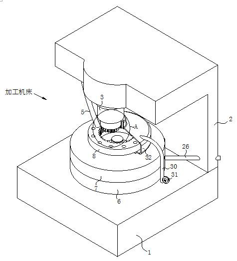
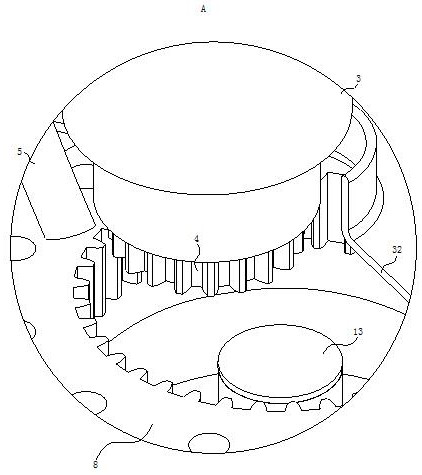
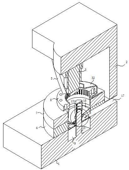
[0033] see Figure 1-12 , the present invention provides a technical solution: a cleaning device for robot reducer shell processing, including a processing machine tool, the processing machine tool includes a workbench 1, a connecting arm 2, a telescopic cylinder 3, a gear shaping blade 4 and a cooling pipe 5, The connecting arm 2 is fixedly connected to the upper end of the workbench 1, the telescopic cylinder 3 is fixedly connected to the bottom of the connecting...


PUM


Abstract

The invention discloses a cleaning device for robot speed reducer shell machining, and belongs to the technical field of speed reducer shell machining. The cleaning device comprises a machining machine tool, wherein the machining machine tool comprises a workbench, a connecting arm, an extendable air cylinder, a gear shaping blade and a cooling pipe, wherein the connecting arm is fixedly connected to the upper end of the workbench, the extendable air cylinder is fixedly connected to the bottom of the connecting arm, the gear shaping blade is fixedly connected to the bottom of the extendable air cylinder, and the cooling pipe is fixedly connected to the bottom of the connecting arm. According to the cleaning device, a screen plate is designed into a fan-shaped combined plate, generated scrap iron is moved to one side by rotating screen plates after each time of gear shaping is finished, on one hand, the scrap iron is conveniently cleaned, extrusion breakage is avoided, on the other hand, the scrap iron is sucked and collected through an air suction pipe, the scrap iron is conveniently and directly sucked away, and cannot fly around; scrap iron cleaning and gear shaping work are carried out at the same time, the machine does not need to be shut down, the production process cannot be influenced, and the production efficiency is improved.

Description

technical field [0001] The invention relates to the technical field of reducer housing processing, in particular to a cleaning device for robot reducer housing processing. Background technique [0002] At present, robots generally use RV reducers. RV reducers are small in size, light in weight, large in speed ratio, high in rigidity, stable in startup, accurate in positioning, and strong in controllability. Therefore, they are widely used in joints of industrial robots to realize motion. The precise transmission of instructions and instructions can complete the precise and complicated work; the structure of the RV reducer is complex, including pinion housings, needle rollers, cycloidal wheels, three crankshafts, planetary frames, and two gears installed between the crankshafts and the planetary frames. A pair of tapered roller bearings, two pairs of cylindrical roller bearings installed between the crank shaft and the cycloid wheel, and two pairs of angular contact ball bear...

Claims


Application Information

Patent Timeline
Patent Type & Authority Applications(China)
IPC IPC(8): B23Q11/00B01D33/17B01D33/76B01D33/44
CPCB23Q11/0046B01D33/17B01D33/76B01D33/44Y02P70/10
Inventor 葛晓敏
Owner 昂越(上海)机械有限公司
Why Eureka
Try Eureka