a diaphragm spring

A diaphragm type, diaphragm technology, applied in leaf springs, springs, springs/shock absorbers, etc., can solve problems such as up and down bumps, circuit board scratches, wheel electrodes unable to rotate, etc., to ensure stability, prevent Caton, the effect of ensuring good contact

Active Publication Date: 2020-05-05
ANHUI TATFOOK OPTOELECTRONICS TECH
View PDF6 Cites 0 Cited by
  • Summary
  • Abstract
  • Description
  • Claims
  • Application Information

AI Technical Summary

Problems solved by technology

The wheel electrode is installed on the shaft, and the installation aperture of the wheel electrode is larger than the diameter of the shaft, and the circuit board often bumps up and down during the transmission process on the assembly line. There are two situations: 1. Wheel type The electrode cannot be in effective contact with the detection point of the circuit; 2. The wheel electrode is stuck by the shaft and cannot rotate, causing it to press on the circuit board and cause scratches to the circuit board

Method used


Image

  • a diaphragm spring
  • a diaphragm spring
  • a diaphragm spring

Examples


Embodiment 1

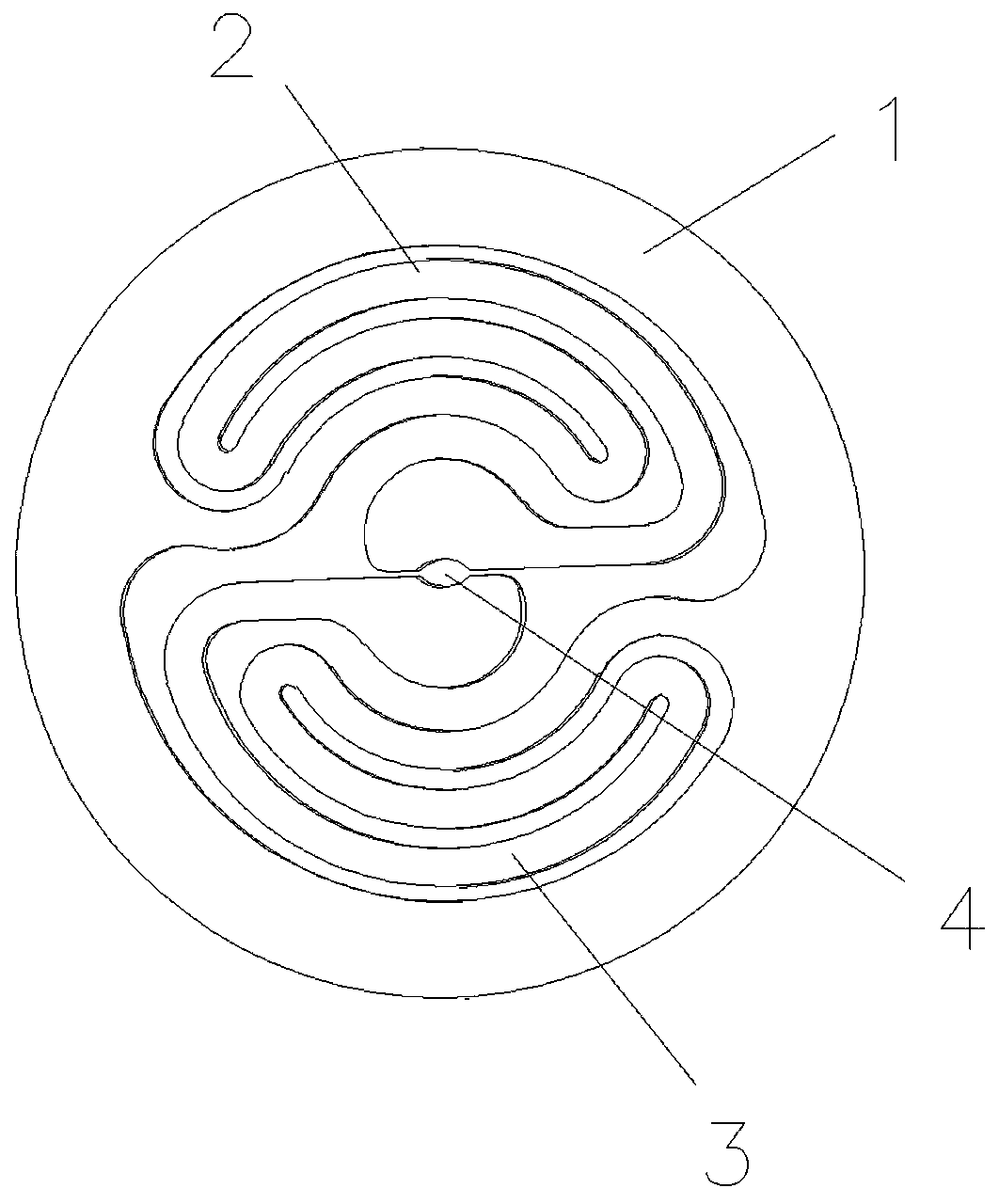
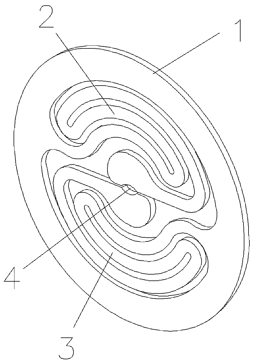
[0015] combine figure 1 and figure 2 As shown, the present invention provides a diaphragm spring, including a contour diaphragm 1, and the contour diaphragm 1 is provided with an elastic deformation part, and the elastic deformation part includes a first elastic rib 2 and a second elastic rib that are reversely symmetrical. Bar 3, the two elastic ribs are in a curved shape, one end of the two elastic ribs is respectively connected to the contour diaphragm, and the other end of the two elastic ribs touches at the center of the contour diaphragm to form an assembly hole 4; assembly The hole 4 can be matched with the shaft of the wheel electrode; the contour diaphragm 1 and the two elastic ribs are an integrated structure.

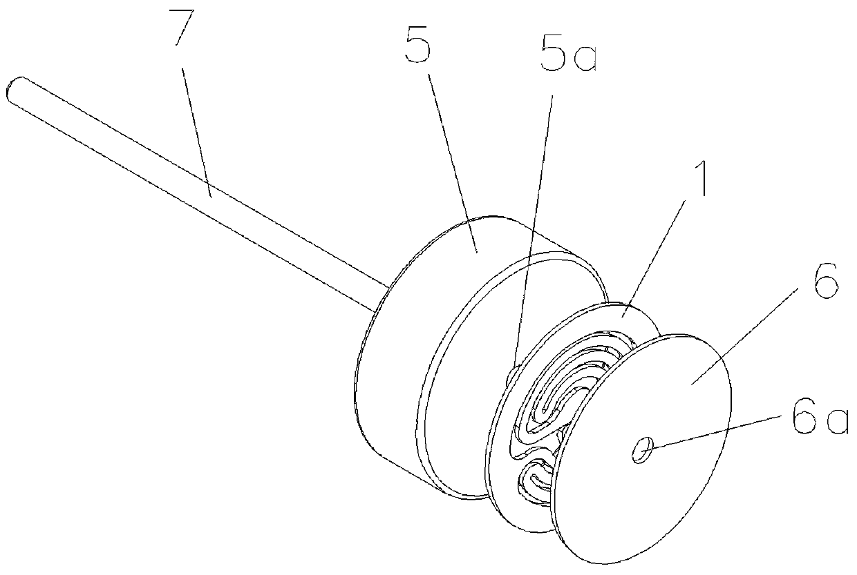
[0016] combine image 3 As shown, when in use, the outer side of the diaphragm spring is welded to the wheel electrode 5, and the diaphragm spring and the wheel electrode 5 are arranged concentrically. In order to prevent the elastic ribs from bending in t...

Embodiment 2

[0019] combine Figure 4 As shown, the present invention provides a diaphragm spring, comprising the same profile diaphragm 1 as in Embodiment 1, and an elastic deformation part is arranged in the contour diaphragm 1, and the elastic deformation part includes a spiral elastic rib 8, elastic The outer end of the rib 8 is connected with the profile diaphragm, and the inner end of the elastic rib 8 is provided with a mounting piece 9, and the mounting plate 9 is provided with an assembly hole 10 concentric with the profile diaphragm, and the assembly hole 10 can be connected with the wheel type. The shaft 6 of the electrode forms a fit; the contour membrane, the elastic rib 8 and the mounting piece 9 are of an integrated structure. The installation and use method of this embodiment is the same as that of Embodiment 1, and will not be repeated here.


PUM


Abstract

The invention discloses a diaphragm type spring comprising a contour diaphragm. The interior of the contour diaphragm is provided with an elastic deformation portion, the elastic deformation portion comprises a first elastic fillet and a second elastic fillet arranged symmetrically in reverse direction, the two elastic fillets are in a curving shape, one ends of the two elastic fillets are separately connected with the contour diaphragm and the other ends of the two elastic fillets are at the center of the contour diaphragm and form an assembly hole; the assembly hole can cooperate with a shaft of a wheel type electrode; the contour diaphragm and the two elastic fillets are integrated structure; when in use, the spring side of the diaphragm is welded with the wheel type electrode, the diaphragm type spring and the wheel type electrode are concentrically arranged, and the shaft of the wheel type electrode penetrates into the assembly hole. When a circuit board bumps up and down when transmitted on the assembly line due to the deformation of the elastic fillets, the wheel type electrode can be raised and lowered with the up-and-down bumping of the circuit board to ensure the good contact between wheel electrode and the circuit board, prevent the stuttering phenomenon and ensure the stability of the test.

Description

technical field [0001] The invention relates to a diaphragm spring. Background technique [0002] In the application detection of various circuits, wheel electrodes are often used to facilitate online detection of circuits. The wheel-type electrode is installed on the shaft. The installation aperture of the wheel-type electrode is larger than the diameter of the shaft, and the circuit board often bumps up and down during the transmission process on the assembly line. There are two situations: 1. Wheel-type The electrode cannot effectively contact the detection point of the circuit; 2. The wheel electrode is stuck by the shaft and cannot rotate, resulting in pressing on the circuit board and causing scratches to the circuit board. Contents of the invention [0003] The purpose of the present invention is to provide a diaphragm spring, which is installed on the wheel electrode, which can ensure good contact between the wheel electrode and the circuit board, prevent the jamm...

Claims


Application Information

Patent Timeline
IPC IPC(8): F16F1/18
CPCF16F1/182
Inventor 许彦斌
Owner ANHUI TATFOOK OPTOELECTRONICS TECH
Why Eureka
Try Eureka