Carbon slag cleaning device for carbon-fired boiler equipment
What is Al technical title?
Al technical title is built by PatSnap Al team. It summarizes the technical point description of the patent document.
A boiler equipment and cleaning device technology, applied in lighting and heating equipment, combustion product treatment, combustion methods, etc., can solve the problems of simple structure, single use function, inconvenient adjustment of the length of use, etc., to achieve convenient cleaning and replacement , increase the use distance, and facilitate the use of the effect
Active Publication Date: 2020-07-17
芜湖天火新能源科技有限公司
View PDF4 Cites 0 Cited by
Summary
Abstract
Description
Claims
Application Information
AI Technical Summary
This helps you quickly interpret patents by identifying the three key elements:
Problems solved by technology
Method used
Benefits of technology
Problems solved by technology
[0005] The purpose of the present invention is to provide a carbon slag cleaning device for carbon-fired boiler equipment to solve the problem that the carbon slag cleaning device currently on the market proposed by the above-mentioned background technology has a simple structure, is inconvenient to adjust the length of use, and has a single function.
Method used
Image
Click on the blue label to locate the original text in one second.
Reading with bidirectional positioning of images and text.
Examples
Embodiment Construction
[0023] The following will clearly and completely describe the technical solutions in the embodiments of the present invention with reference to the accompanying drawings in the embodiments of the present invention. Obviously, the described embodiments are only some, not all, embodiments of the present invention. Based on the embodiments of the present invention, all other embodiments obtained by persons of ordinary skill in the art without making creative efforts belong to the protection scope of the present invention.
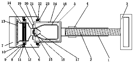
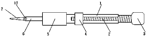
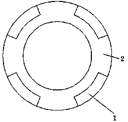
[0024] see Figure 1-3 , the present invention provides a technical solution: a carbon slag cleaning device for carbon-fired boiler equipment, including a first connecting rod 1, a second connecting rod 2, a pull ring 3, a collar 4, a casing 5, and a first connecting plate 6 , the second connecting plate 7, the first connecting block 8, the dust suction net 9, the air duct 10, the fan 11, the first rotating shaft 12, the wind plate 13, the filter bag 14, the f...
PUM
Abstract
The invention discloses a carbon residue cleaning device for a carbon burning boiler device. The carbon residue cleaning device comprises a first connecting rod, a dust collecting net, an air guidingduct and an air outlet net, wherein one side of the first connecting rod is provided with a second connecting rod, the side, far away from the first connecting rod, of the second connecting rod is provided with a pull ring, the outer side, far away from the second connecting rod, of the first connecting rod is provided with a lantern ring, a shell is far away from the side, connected with the first connecting rod, of the lantern ring, a first connecting plate is arranged on the side, far away from the first connecting rod, of the shell, and a second connecting plate is arranged on the side, far away from the shell, of the first connecting plate; and the side, close to the first connecting plate, of the second connecting plate is provided with a first connecting block. According to the carbon residue cleaning device for the carbon burning boiler device, the lantern ring is rotated to control the second connecting rod to move, the total length of the first connecting rod and the second connecting rod of the device can be longer, the using distance of the device can be increased, and use of the device is facilitated.
Description
technical field [0001] The invention relates to the technical field of carbon slag cleaning, in particular to a carbon slag cleaning device for carbon-fired boiler equipment. Background technique [0002] Coal-fired boiler refers to the coal that is burned as fuel. After the heat of coal is converted, steam or hot water is generated. When burning carbon, a large amount of coal slag and dust will be generated, which needs to be cleaned. [0003] When cleaning the carbon slag, a shovel will be used, so that the carbon slag in the boiler can be easily cleaned. [0004] However, most carbon slag cleaning devices on the market are simple in structure, inconvenient to adjust the length of use, and have a single function. Contents of the invention [0005] The purpose of the present invention is to provide a carbon slag cleaning device for carbon-fired boiler equipment to solve the problem that the carbon slag cleaning device currently on the market proposed by the above-mention...
Claims
Application Information
Patent Timeline
Application Date:The date an application was filed.
Publication Date:The date a patent or application was officially published.
First Publication Date:The earliest publication date of a patent with the same application number.
Issue Date:Publication date of the patent grant document.
PCT Entry Date:The Entry date of PCT National Phase.
Estimated Expiry Date:The statutory expiry date of a patent right according to the Patent Law, and it is the longest term of protection that the patent right can achieve without the termination of the patent right due to other reasons(Term extension factor has been taken into account ).
Invalid Date:Actual expiry date is based on effective date or publication date of legal transaction data of invalid patent.