Anti-rear collision driving assistance device based on 3D grating imaging principle
A technology of grating imaging and driving assistance, applied in signal devices, optics, optical components, etc., can solve problems such as short detection distance, achieve the effect of low manufacturing cost, convenient maintenance and large-scale promotion and use
- Summary
- Abstract
- Description
- Claims
- Application Information
AI Technical Summary
Problems solved by technology
Method used
Image
Examples
specific Embodiment approach 1
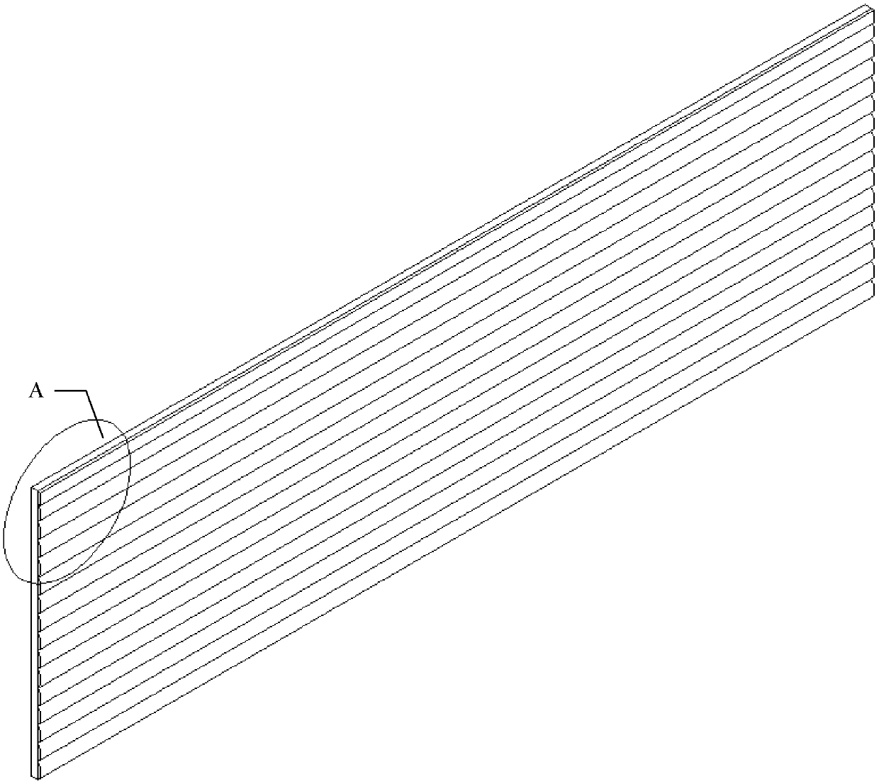
[0026] Specific implementation mode one: refer to Figure 1 to Figure 4 Describe this embodiment in detail. The anti-rear collision driving assistance device based on the 3D grating imaging principle described in this embodiment includes: a stripe picture 1 and a cylindrical lens grating, and the cylindrical lens grating is composed of a plurality of cylindrical lens elements 2;
[0027] The fringe picture 1 is set on the common focal plane of all the cylindrical lens elements 2 in the cylindrical lens grating;
[0028] Stripe painting 1 is composed of two kinds of wide and narrow solid color stripes arranged alternately. The two stripes have different colors.
[0029] The sum of the widths of the two stripes is equal to the grating pitch of the cylindrical lens grating,
[0030] The cross-section of the cylindrical lens element 2 is arcuate, and the arc of the cylindrical lens element 2 is 89°-90°,
[0031] The axes of a plurality of cylindrical lens elements 2 are all para...
specific Embodiment approach 2
[0048] Embodiment 2: This embodiment further explains the anti-rear-collision driving assistance device based on the principle of 3D grating imaging described in Embodiment 1. In this embodiment, it also includes LED lights 3,
[0049] The LED lamp 3 is fixed on the outside of the outermost cylindrical lens unit 2,
[0050] The light emitted by the LED lamp 3 is white light.
[0051] In this embodiment, an LED lamp 3 is added to illuminate the stripe pattern 1 and the plurality of cylindrical lens elements 2 . In actual use, the driver turns on the LED light 3 according to the ambient light conditions so that the driver of the rear car can observe.
specific Embodiment approach 3
[0052] Specific embodiment three: this embodiment is a further description of the anti-rear-collision driving assistance device based on the principle of 3D raster imaging described in specific embodiment one or two. In this embodiment, it also includes a suction cup,
[0053] The suction cup is fixed on the back of the stripe painting 1, and is used for fixing the anti-rear-end collision driving assistance device on the rear of the car.
[0054] The anti-rear collision driving assistance devices are divided into two types, A and B, among which type A is suitable for small passenger cars, and type B is suitable for large passenger cars. The classification methods and heights from the ground are shown in the table:
[0055] Table 1 Installation location
[0056] Types of rear-end collision prevention aids
Install the model
Height from the ground (m)
First
A.C
0.5
Second
B.D
1.9
[0057] The height from the ground is the height ...
PUM
 Abstract
Description
Claims
Application Information
 - R&D
- Intellectual Property
- Life Sciences
- Materials
- Tech Scout
- Unparalleled Data Quality
- Higher Quality Content
- 60% Fewer Hallucinations
Browse by: Latest US Patents, China's latest patents, Technical Efficacy Thesaurus, Application Domain, Technology Topic, Popular Technical Reports.
© 2025 PatSnap. All rights reserved.Legal|Privacy policy|Modern Slavery Act Transparency Statement|Sitemap|About US| Contact US: help@patsnap.com


