A Mechanism for Measuring Starting Torque and Constant Torque and Measuring Rotation Angle

A technology of starting torque and rotation angle, which is applied in the direction of force/torque/work measuring instruments, measuring devices, and testing of mechanical components. It can solve problems such as excessive deviation, invalid measurement results, and only angle measurement, so as to reduce manufacturing. Cost, simplification of complexity, effect of reduced manipulation

Active Publication Date: 2021-06-29
合肥森曼智能科技有限公司
View PDF10 Cites 0 Cited by
  • Summary
  • Abstract
  • Description
  • Claims
  • Application Information

AI Technical Summary

Problems solved by technology

[0003] Now in the industry to measure the rotation angle of the gear clearance, there is generally no fixed torque requirement, and the angle value measured by the seat when the gear is meshed and squeezed is used. Another method is to add a set of torque sensors to read the angle when the torque is reached. Neither of the two measurement methods can closely follow the actual working conditions of the gear, so the actual gear clearance cannot be measured
[0004] In addition, in the past, the angle sensor and the measuring shaft were rigidly connected, so that only the angle could be measured, and the starting torque could not be measured by infinite rotation.
Because the angle sensor is limited by the measurement angle range, if the rotation angle exceeds the measurement range, it may cause invalid measurement results or even damage the sensor
When measuring the angle with rigid connection, after the measurement of the measuring axis is completed, when returning to the position, the return position is not accurate, and the starting point of the next measurement will be different. After multiple consecutive measurements, the starting point of the angle sensor will deviate too much, so Will result in invalid measurement results, or even damage the sensor

Method used


Image

  • A Mechanism for Measuring Starting Torque and Constant Torque and Measuring Rotation Angle
  • A Mechanism for Measuring Starting Torque and Constant Torque and Measuring Rotation Angle
  • A Mechanism for Measuring Starting Torque and Constant Torque and Measuring Rotation Angle

Examples


Embodiment Construction

[0017] In order to have a further understanding and understanding of the structural features of the present invention and the achieved effects, the preferred embodiments and accompanying drawings are used for a detailed description, as follows:

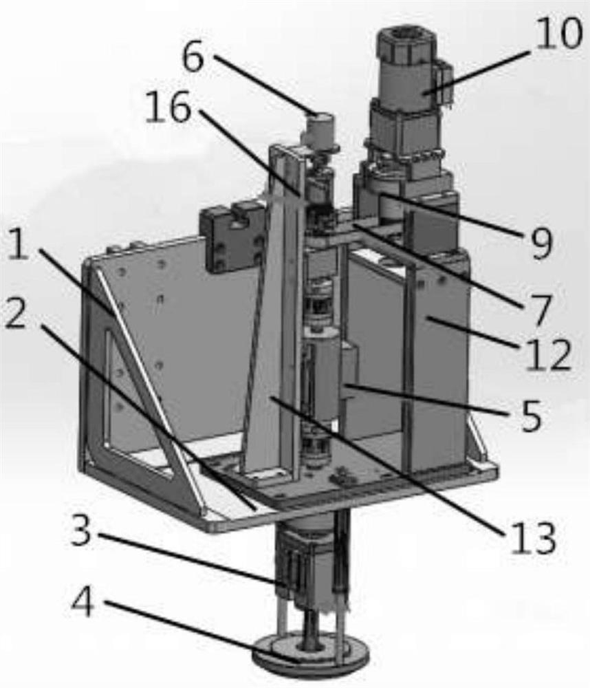
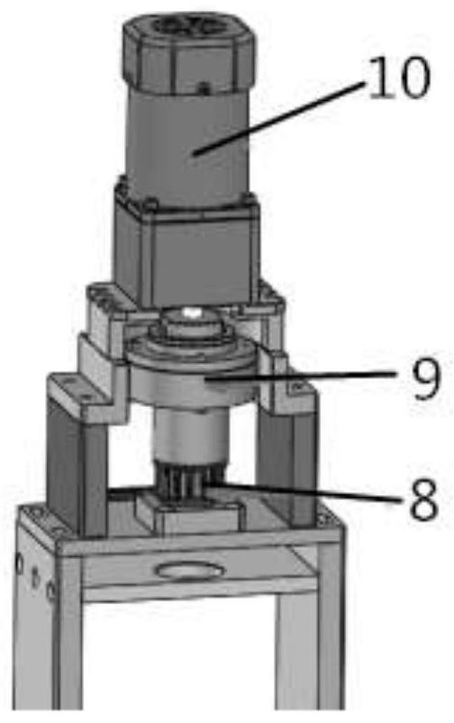
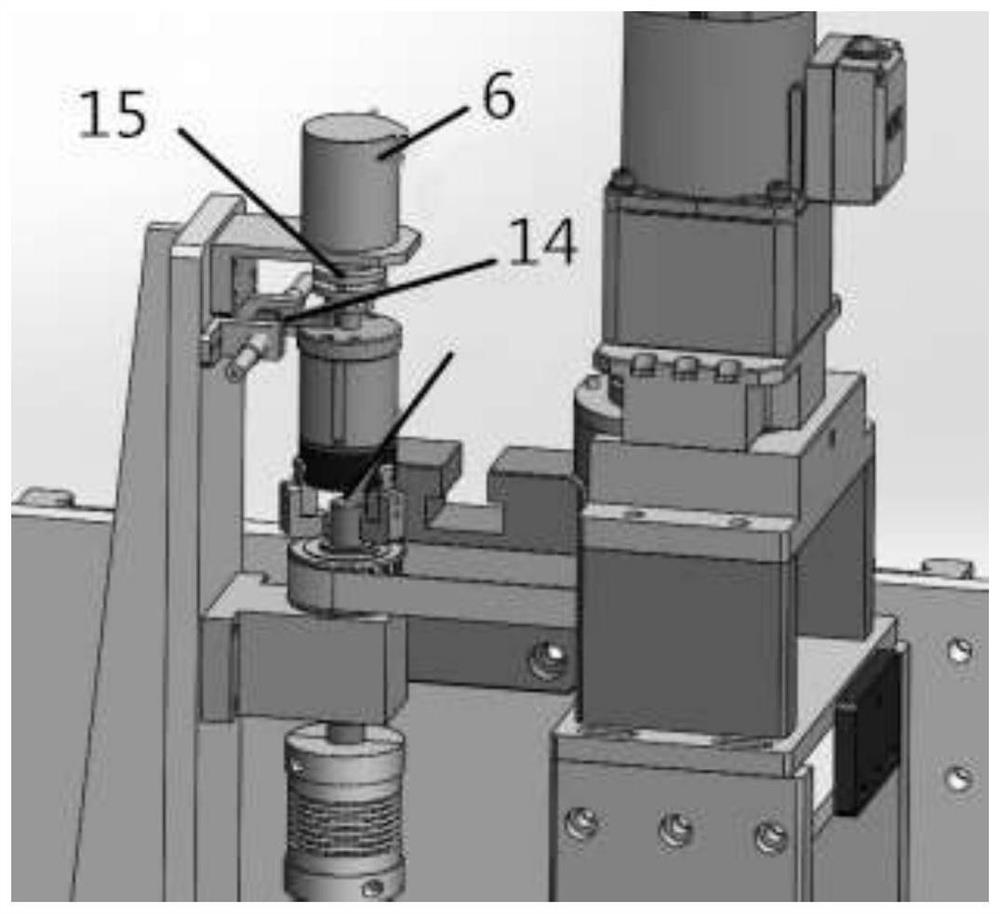
[0018] Refer to attached Figure 1-3 As shown, a mechanism for measuring the starting torque and constant torque for measuring the rotation angle includes a frame 1, the bottom plate 2 of the frame 1 is provided with a measuring shaft 3, and the bottom end of the measuring shaft 3 is set through the bottom plate 2 , the bottom end of the measuring shaft 3 is provided with a gear drive head 4, the measuring shaft 3 is provided with a torque sensor 5, the torque sensor 5 is arranged above the bottom plate 2, and the measuring shaft 3 is An angle sensor 6 is also provided, and the angle sensor 6 is set on the top of the measuring shaft 3, and the measuring shaft 3 is also sleeved with a timing belt 7, and the timing belt 7 is sleeved on ...


PUM


Abstract

The invention discloses a mechanism for measuring starting torque and constant torque and measuring rotation angle, which comprises a frame. A measuring shaft is arranged on the bottom plate of the frame. , the measuring shaft is provided with a torque sensor, the torque sensor is located above the bottom plate, the measuring shaft is also provided with an angle sensor, the angle sensor is located at the top of the measuring shaft, and the measuring shaft is also provided with a synchronous belt, the synchronous belt Set on the synchronous belt pulley, a torque limiting mechanism is arranged above the synchronous belt pulley, the torque limiting mechanism is connected with the synchronous belt pulley, and a driving motor is arranged above the torque limiting mechanism. Compared with the existing technology, this mechanism realizes one piece of equipment and one set of measurement components to complete the measurement of two sets of data, which greatly simplifies the complexity of the equipment, reduces the manufacturing cost of the equipment, reduces the operation action, and improves the stability of the equipment .

Description

technical field [0001] The invention relates to the technical field of automobile assembly, in particular to a mechanism for measuring starting torque and constant torque and measuring rotation angle. Background technique [0002] After the differential gear assembly is completed, it is necessary to measure the measured starting torque and gear meshing angle values ​​to check whether the gears are properly mated. In the past, this required two devices or one device with two independent stations to complete the measurement. Therefore, it is necessary to design a component to realize the measurement of two sets of data by one device and one measurement component, which greatly simplifies the complexity of the device, reduces the manufacturing cost of the device, reduces the operation action, and improves the stability of the device. [0003] Now in the industry to measure the rotation angle of the gear gap, there is generally no fixed torque requirement, and the angle value m...

Claims


Application Information

Patent Timeline
Patent Type & Authority Patents(China)
IPC IPC(8): G01M13/021G01L5/00G01B21/22
CPCG01B21/22G01L5/0042G01M13/021
Inventor 徐福根宋增广韩晓东胡亮赵学学
Owner 合肥森曼智能科技有限公司
Why Eureka
Try Eureka