
Button panel and switch panel

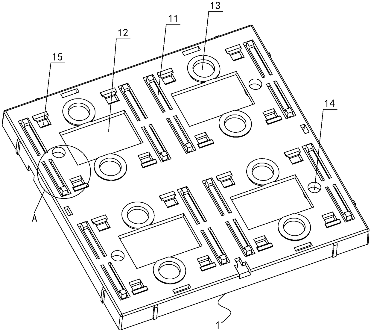
A switch panel and button technology, which is applied in the direction of electric switches, electrical components, circuits, etc., can solve the problems of high cost of the button panel, affecting the backlight effect of the switch panel, and complicated installation process, so as to simplify the installation process, avoid occlusion, and improve the backlight effect of effect

Pending Publication Date: 2019-03-01
广州河东科技有限公司
View PDF10 Cites 1 Cited by
  • Summary
  • Abstract
  • Description
  • Claims
  • Application Information

AI Technical Summary

Problems solved by technology

[0003] The purpose of the present invention is to provide a button panel and a switch panel, which can solve the problems of the existing switch panel, such as high cost of the button panel, complicated installation process, and affecting the backlight effect of the switch panel

Method used


Image

  • Button panel and switch panel
  • Button panel and switch panel
  • Button panel and switch panel

Examples


Embodiment Construction

[0024] In order to make the technical problems solved by the present invention, the technical solutions adopted and the technical effects achieved clearer, the technical solutions of the embodiments of the present invention will be further described in detail below in conjunction with the accompanying drawings. Obviously, the described embodiments are only the technical solutions of the present invention. Some, but not all, embodiments. Based on the embodiments of the present invention, all other embodiments obtained by those skilled in the art without creative efforts fall within the protection scope of the present invention.

[0025] In the description of the present invention, unless otherwise clearly stipulated and limited, the terms "connected" and "fixed" should be understood in a broad sense, for example, it can be a fixed connection, a detachable connection, or an integrated It can be mechanically connected or electrically connected; it can be directly connected or ind...


PUM


Abstract

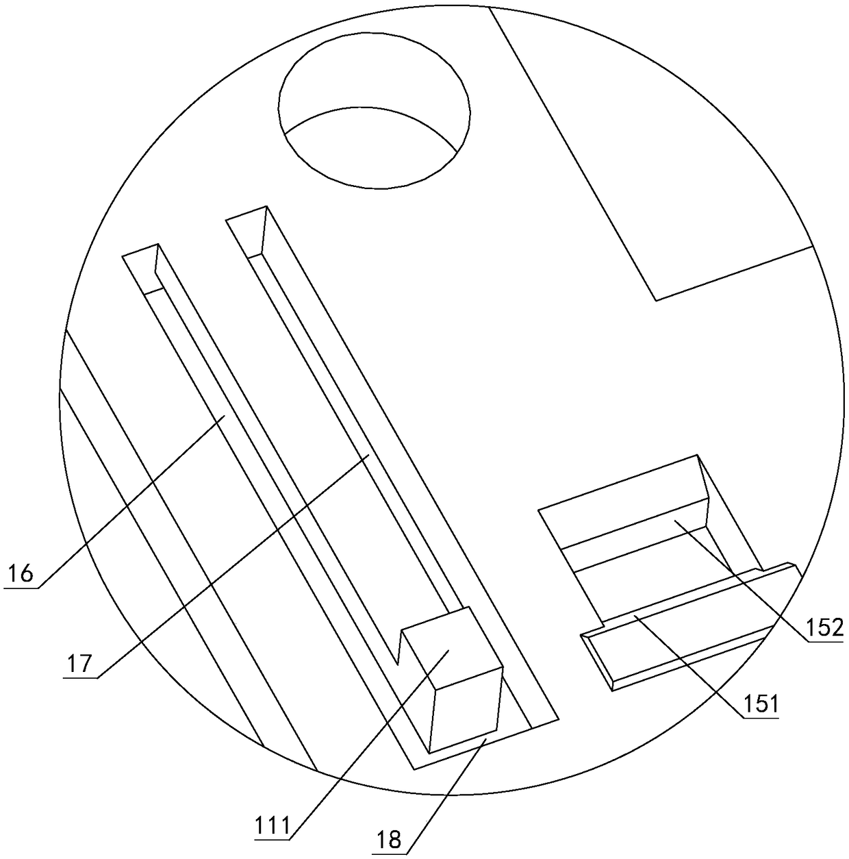
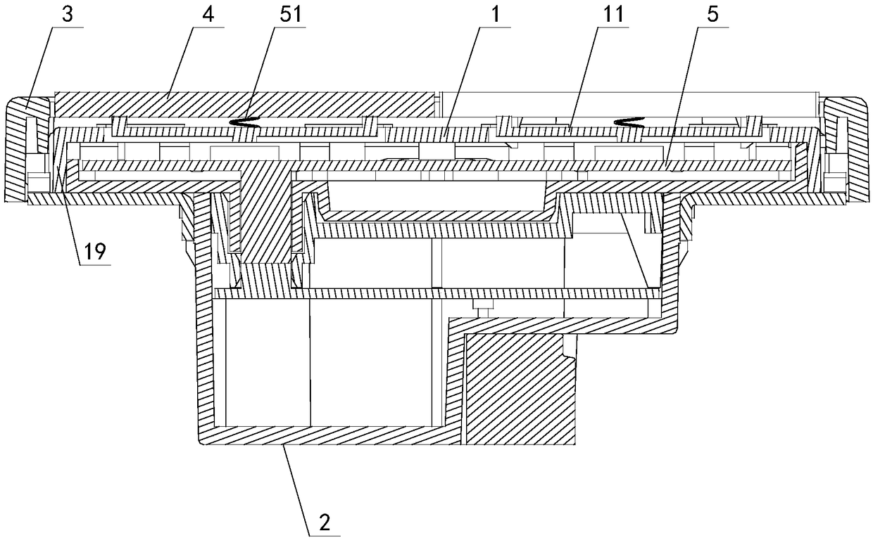
The invention discloses a button panel, which is used for installing buttons. The button panel is provided with elastic parts used for supporting buttons, wherein the elastic parts are arranged on positions corresponding to the buttons on the button panel and form an integral structure with the button panel; one end of each elastic part is connected with the button panel, and the other end is suspended; and the surface, which faces the button, of each elastic part is extruded out of the surface of the button panel. The invention also discloses a switch panel, which comprises a control module,a panel shell, a PCB (Printed Circuit Board), the button panel and a button capable of being connected to the button panel in a pressing way, wherein the PCB is arranged in the panel shell and is electrically connected with the control module out of the panel shell; the PCB is provided with a signal trigger point; the inner side end surface of the button is provided with a signal trigger part on aposition corresponding to the signal trigger point; and the button panel is the above button panel. The button panel is provided with a trough to form the elastic part, and therefore, a button resetting function can be realized without additional elastic sheets.

Description

technical field [0001] The invention relates to the field of switch panels, in particular to a button panel and a switch panel using the same. Background technique [0002] At present, in switch panel products, the keys are installed on the key panel, and the button reset function is realized through the shrapnel independently installed on the key panel. This kind of structural design not only has a large production cost, but also has a complicated installation process. In addition, for some switch panels with backlight effects, the independently installed shrapnel will block the light source inside the switch panel, thereby affecting the backlight effect. The above-mentioned problems existing in the prior art urgently need to be solved. Contents of the invention [0003] The purpose of the present invention is to provide a key panel and a switch panel, which can solve the problems of the existing switch panel, such as high cost of the key panel, complicated installation ...

Claims


Application Information

Patent Timeline
Patent Type & Authority Applications(China)
IPC IPC(8): H01H13/02H01H13/04H01H13/14
CPCH01H13/02H01H13/04H01H13/14
Inventor 杜其昌蔡堪永李云飞刘毅
Owner 广州河东科技有限公司
Learn More