
Semiconductor storage device and resetting method for a semiconductor storage device

a semiconductor storage device and storage device technology, applied in digital storage, pulse automatic control, instruments, etc., can solve the problems of power consumption increase, reset operation itself becomes a source of noise, and the reset operation cannot be accurately operated, so as to achieve the effect of reset the controller setting the internal operation

Inactive Publication Date: 2009-07-02
RENESAS ELECTRONICS CORP
View PDF5 Cites 4 Cited by
  • Summary
  • Abstract
  • Description
  • Claims
  • Application Information

AI Technical Summary

Benefits of technology

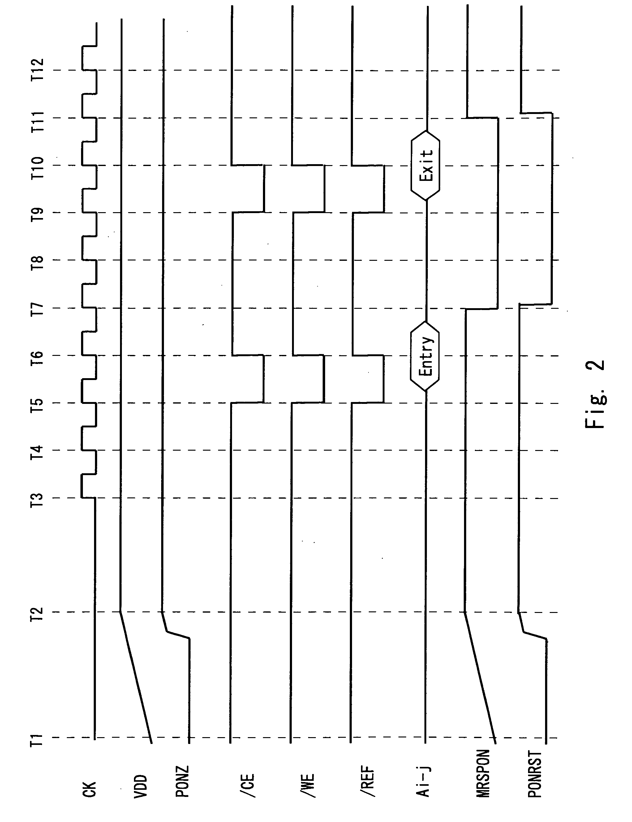
[0012]A first exemplary aspect of an embodiment of the present invention is a semiconductor storage device, including a voltage detector that outputs a first reset signal in accordance with a level of a power supply voltage, a command decoder that moves to a mode set state in accordance with input of an external control pin and outputs mode set information in accordance with a command input from an address pin, a mode register set circuit that outputs a mode reset signal in accordance with the mode set information, and a reset circuit that outputs a second reset signal initializing an internal operation set circuit in accordance with the mode reset signal and the first reset signal. It is possible to initialize the controller setting the internal operation by the second reset signal separately from the first reset signal.
[0013]According to the present invention, it is possible to reliably reset the controller setting the internal operation in the soft reset.

Problems solved by technology

Thus, when the power-on signal is again generated from the mode register set command, the soft reset cannot be accurately operated.
This is because the power supply has already been supplied enough and the system of the whole memory is reset at a voltage higher than the starting operation; therefore, the power consumption increases and the reset operation itself becomes a source of the noise.
Further, in recent years, the memory capacity has been increasing and the circuit configuration has been complicated, which increases the time required for the starting operation after the power-on.
The present inventors have thus found a problem that it is difficult to reliably reset the controller setting the internal operation in the soft reset.

Method used


Image

  • Semiconductor storage device and resetting method for a semiconductor storage device
  • Semiconductor storage device and resetting method for a semiconductor storage device
  • Semiconductor storage device and resetting method for a semiconductor storage device

Examples


first exemplary embodiment

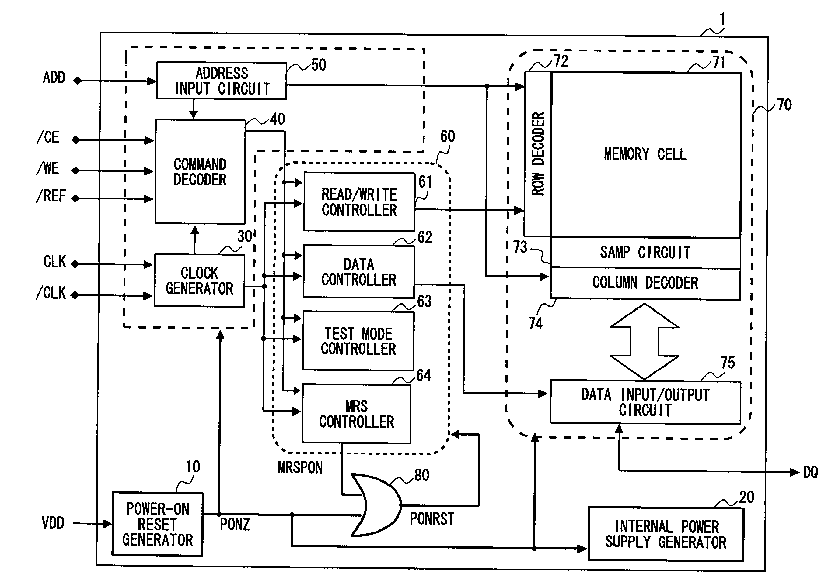
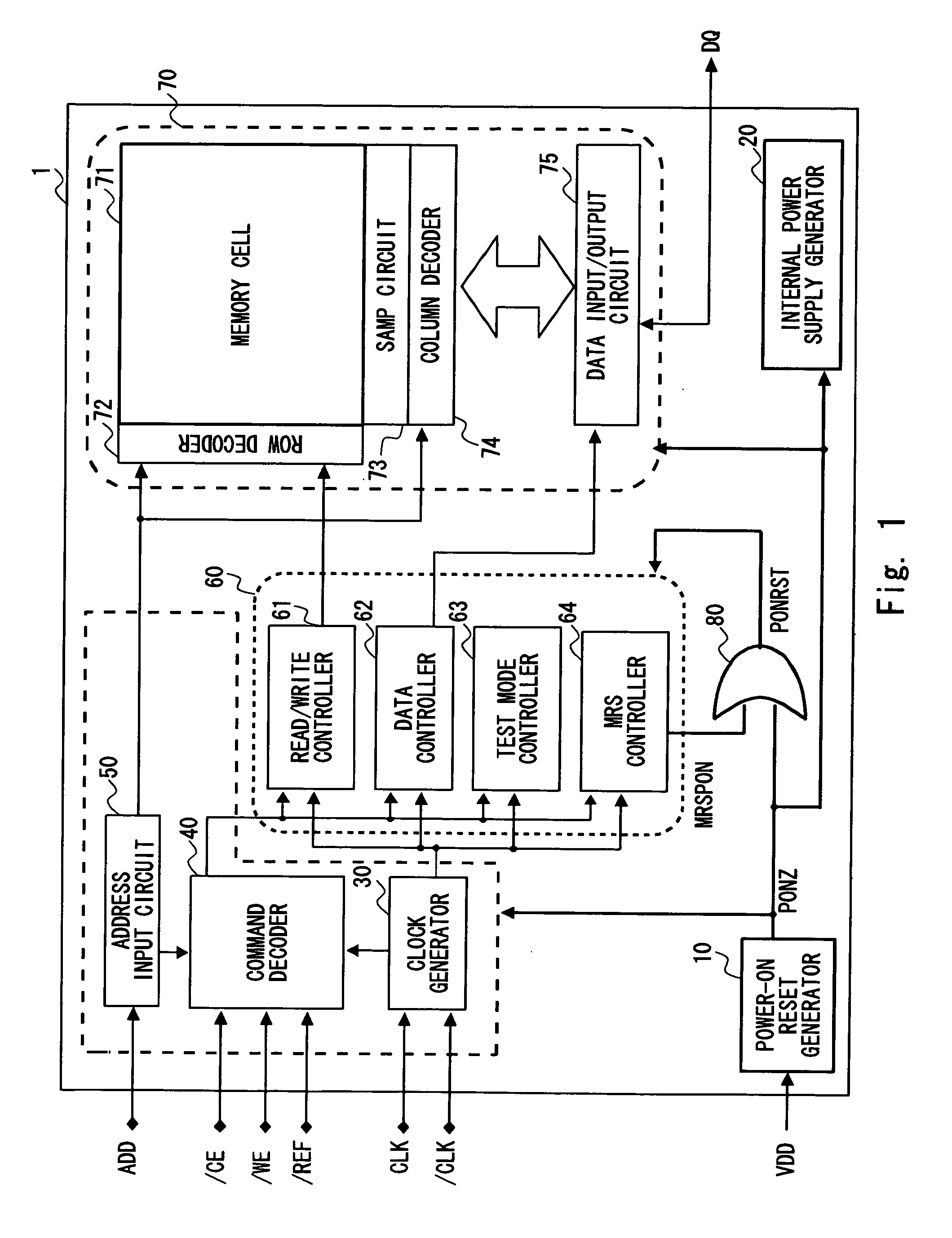
[0020]FIG. 1 is a block diagram showing a configuration example of a semiconductor device of a memory according to a first exemplary embodiment of the present invention. A semiconductor device 1 shown in FIG. 1 includes a power-on reset generator (voltage detector) 10, an internal power supply generator 20, a clock generator 30, a command decoder 40, an address input circuit 50, an operation control section 60, a memory section 70, and a reset circuit (OR circuit) 80. In the first exemplary embodiment, the operation control section (internal operation set circuit) 60 includes a read / write controller 61, a data controller 62, a test mode controller 63, and an MRS (Mode Resister Set) controller (mode register set circuit) 64, as an example. Further, in the first exemplary embodiment, the memory section 70 includes a memory cell 71, a row decoder 72, an SAMP circuit 73, a column decoder 74, and a data input / output circuit 75.

[0021]The clock generator 30 generates a clock (local clock) ...


PUM


Abstract

An exemplary aspect of an embodiment of the present invention is a semiconductor storage device including a power-on reset generator that outputs a first reset signal in accordance with a level of a power supply voltage, a command decoder that moves to a mode set state in accordance with input of an external control pin and outputs mode set information in accordance with a command input from an address pin, an MRS controller that outputs a mode reset signal (MRSPON signal) in accordance with the mode set information, and a reset circuit that outputs a second reset signal initializing each circuit of an operation control section in accordance with the mode reset signal and the first reset signal.

Description

BACKGROUND[0001]1. Field of the Invention[0002]The present invention relates to a semiconductor storage device, and more particularly, to a semiconductor storage device including a power-on reset circuit inside thereof.[0003]2. Description of Related Art[0004]In a system including a semiconductor storage device (hereinafter referred to as memory), the whole system may be hung up by unexpected events (system abnormal operation, power supply drop due to noise, and so on) during the operation. In this case, it is needed to execute a soft reset by external control as a memory setting state becomes unclear, so as to reliably reset the internal part of the memory.[0005]FIG. 3 is a diagram showing a configuration example of a semiconductor device of a memory according to a related art. When the power is turned on, an initialization process of each circuit is executed by a power-on reset signal (PONZ signal). Further, when a mode register set command is input from outside after the power is...

Claims


Application Information

Patent Timeline
Patent Type & Authority Applications(United States)
IPC IPC(8): H03L7/00
CPCG11C7/20G11C7/1045
Inventor TAKANO, SUSUMU
Owner RENESAS ELECTRONICS CORP
Learn More