Prefill valve

A liquid-filled valve and valve body technology, which is applied in the field of hydraulic devices, can solve problems such as thin connection between the pilot valve core and the ejector rod, complex shape of the main valve core, and falling off of the pilot valve core, so as to achieve outstanding substantive features, save materials, Reset Reliable Effects

Inactive Publication Date: 2005-09-07
王诚谦
View PDF0 Cites 4 Cited by
  • Summary
  • Abstract
  • Description
  • Claims
  • Application Information

AI Technical Summary

Problems solved by technology

The pilot spool of this filling valve is connected with the ejector rod. Although it can better complete the rapid filling and draining of the hydraulic cylinder, and improve the hydraulic cylinder idle stroke speed and return speed, however, due to the pilot spool and The connection of the ejector rod is relatively thin, and sometimes the pilot valve core will fall off and cause accidents. In addition, the main valve core has a complex shape and is integrated with the main valve rod, which makes processing difficult and wastes materials. This is the existing The main problem with the technology

Method used


Image

  • Prefill valve

Examples


Embodiment Construction

[0008] In order to clearly illustrate the technical features of the solution, the solution will be described below through a specific implementation.

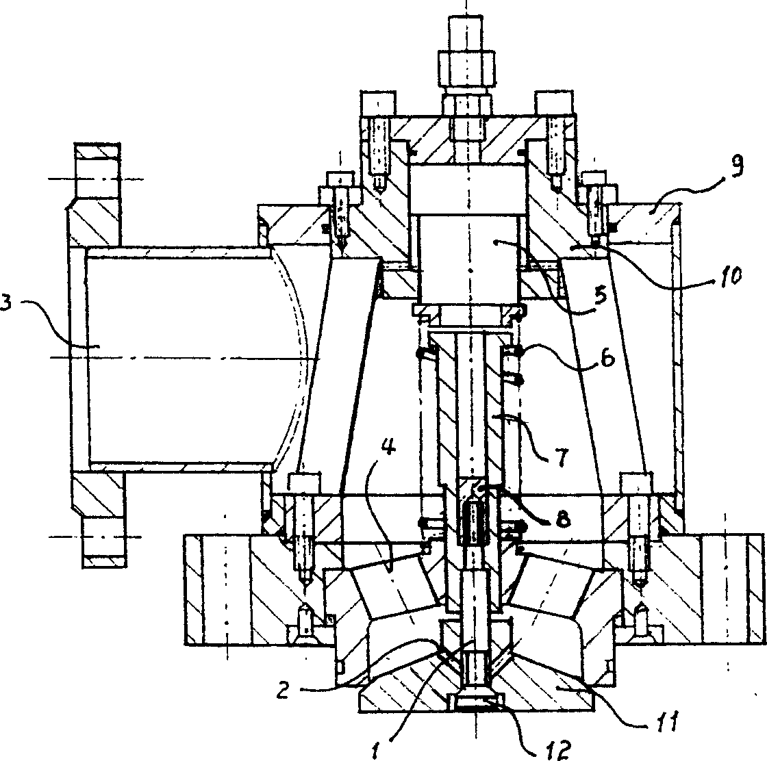
[0009] It can be seen from the accompanying drawings that the liquid filling valve of this program includes a housing (9) and a valve body (10), and a low-pressure oil port (3) communicates with the valve body (10) on the housing (9). Inside the valve body (10) there are control piston (5), spring (6), main spool (11) and the pilot spool (12) at the bottom of the main spool (11), on the valve body (10) there is The oil passage (4) has an oil drain hole (2) on the main spool (11). This scheme is that there is a push rod (7) between the main spool (11) and the control piston (5), the spring (6) is wound on the push rod (7), and the push rod There is a gap between (7) and main valve core (11), and this gap is 2-5 millimeter. The pilot spool (12) at the inner bottom of the main spool (11) has a pilot valve stem (1), and the pilot...


PUM


Abstract

The invention supplies a liquid feeding valve that includes case body and valve body. Low-pressure oil mouth on the case body is connected to the valve body. And control piston, spring, main valve core, and precursor are set in the valve body. The oil drain is set on the main valve core; the oil way is set on the valve body. The feature is that pulling bar is set between the man valve core and the control piston. The spring is enlaced on the bulling bar. A clearance is set between the pulling bar and the main valve core. A precursor valve bar is set on the precursor valve core on the bottom of the main valve core. And the precursor valve bar is fixed through the main valve core and the pulling bar. The clearance between the pulling bar and the main valve core is 2-5mm. The precursor valve fixed to pulling bar by precursor valve fixing nut.

Description

Technical field: [0001] The invention relates to a hydraulic device, especially a liquid filling valve used for fast filling and draining of a hydraulic cylinder and increasing the speed of the empty stroke and the return stroke of the hydraulic cylinder Background technique: [0002] In the prior art, the prior art closest to the present invention is exactly the filling valve used on large hydraulic presses at home and abroad. The pilot spool of this filling valve is connected with the ejector rod. Although it can better complete the rapid filling and draining of the hydraulic cylinder and improve the hydraulic cylinder idle stroke speed and return speed, however, due to the pilot spool and The connection of the ejector rod is relatively thin, and sometimes the pilot valve core will fall off and cause accidents. In addition, the main valve core has a complex shape and is integrated with the main valve rod, which makes processing difficult and wastes materials. This is the e...

Claims


Application Information

Patent Timeline
IPC IPC(8): F16K1/00F16K1/32
Inventor 王诚谦
Owner 王诚谦
Why Eureka
Try Eureka