Power-on reset circuit used for integrated circuit chip

An integrated circuit and electric reset technology, applied in electrical components, electronic switches, pulse technology, etc., can solve problems such as reset circuit misoperation, achieve reliable reset, reduce layout area, and solve the effects of system instability

Active Publication Date: 2016-01-27
RDA MICROELECTRONICS BEIJING
View PDF5 Cites 4 Cited by
  • Summary
  • Abstract
  • Description
  • Claims
  • Application Information

AI Technical Summary

Problems solved by technology

[0005] One of the technical problems to be solved by the present invention is to provide a new power-on reset circuit to solve the misoperation problem of the existing reset circuit

Method used


Image

  • Power-on reset circuit used for integrated circuit chip
  • Power-on reset circuit used for integrated circuit chip
  • Power-on reset circuit used for integrated circuit chip

Examples


Embodiment Construction

[0027] The implementation of the present invention will be described in detail below in conjunction with the accompanying drawings and examples, so as to fully understand and implement the implementation process of how to apply technical means to solve technical problems and achieve corresponding technical effects in the present invention. The embodiments of the present application and the various features in the embodiments can be combined with each other under the premise of no conflict, and the formed technical solutions are all within the protection scope of the present invention.

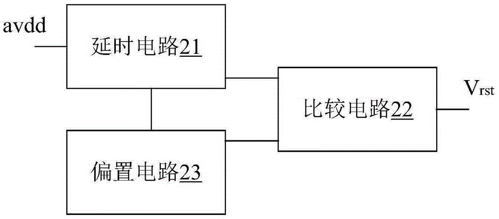
[0028] Such as figure 2 As shown, the power-on reset circuit of the embodiment of the present application includes a delay circuit 21, a comparison circuit 22 and a bias circuit 23. The power-on reset circuit receives the input power supply voltage avdd, and outputs a stable reset signal Vrst, which is combined below image 3 , Figure 4 , Figure 5 Describe in detail.

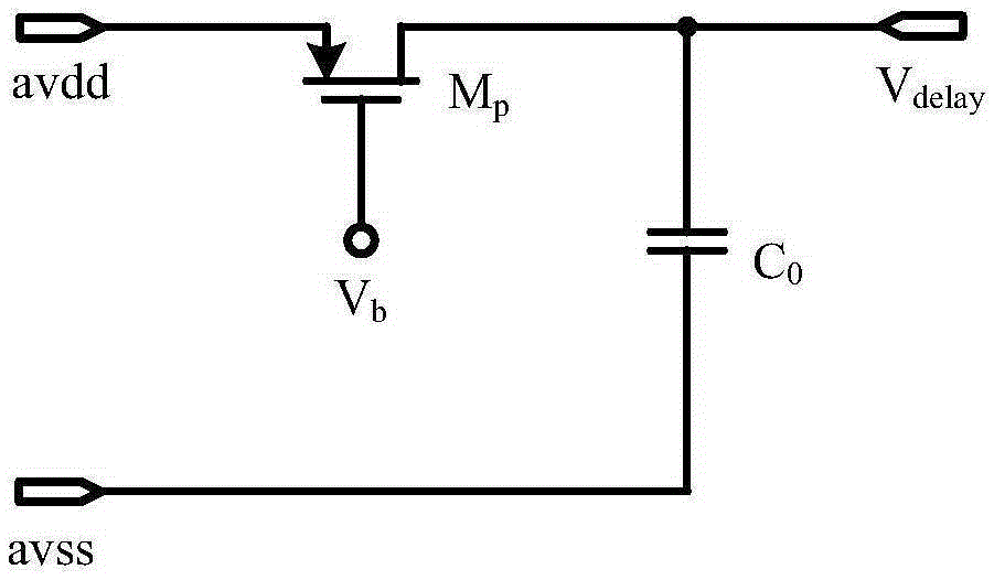
[0029] The delay ci...


PUM


Abstract

The invention provides a power-on reset circuit used for an integrated circuit chip. The power-on reset circuit comprises a delay circuit, a comparison circuit and a biasing circuit. The delay circuit enables input power supply voltage to form delayed voltage signals with certain time delay. The comparison circuit receives the delayed voltage signals and outputs reset signals when the delayed voltage signals are greater than set voltage values. The biasing circuit provides the set voltage values for the comparison circuit. The power-on reset circuit effectively reduces the layout area of circuits, solves the problem of system instability caused by power glitches, can achieve reliable reset even during slow rise of power supply and is easy to popularize and implement.

Description

technical field [0001] The invention relates to the technical field of integrated circuits, in particular to a power-on reset circuit used in integrated circuit chips. Background technique [0002] In electronic systems, the power-on reset circuit is one of the most commonly used circuit modules. It can generate a reset signal during the power-on process and perform reset operations on other modules of the circuit, thereby eliminating the inconsistency of the circuit modules at the initial power-on. steady state. In a circuit system including units such as registers, latches, and flip-flops, a power-on reset signal is required to initialize or reset these units. [0003] Most power-on reset circuits use a time delay mechanism to generate a reset signal, such as figure 1 shown. figure 1 It is a basic reset circuit, which uses the charging of the capacitor in the RC circuit to realize the delay of the signal. This circuit structure has the following problems. On the one ha...

Claims


Application Information

Patent Timeline
Patent Type & Authority Applications(China)
IPC IPC(8): H03K17/22
Inventor 武振宇王宇晨陈建华
Owner RDA MICROELECTRONICS BEIJING
Why Eureka
Try Eureka