Low Phase-Noise Oscillator

a low-phase noise, oscillator technology, applied in the field of oscillators, can solve the problems of unpredictable oscillation frequency and i/q 90° phase ambiguity, the use of polyphase filters, and the cost of increasing power dissipation and sensitivity to component mismatches, so as to reduce the impact of injected noise, and reduce the effect of i/q mismatch

Inactive Publication Date: 2008-06-19
WILLSON ALAN N JR
View PDF5 Cites 41 Cited by
  • Summary
  • Abstract
  • Description
  • Claims
  • Application Information

AI Technical Summary

Benefits of technology

[0011]A new quadrature-phase oscillator achieving a noise factor close to the theoretical minimum value of 1+γ is presented. The tail tanks serve dual purposes in phase noise reduction. First, they provide additional energy storage to force noise current redistribution and, as a result, the noise current injected into the main tank is reduced. Second, they provide a noise canceling mechanism to reduce the impact of injected noise when a transistor is operating in the triode region. The tail tank causes a built-in negative feedback mechanism to limit the current consumption in this oscillator. As a result, the figure-of-merit doesn't drop with the increase of transistor size as it would in a conventional oscillator. Therefore, transistors can be sized large to reduce I / Q mismatch. The optimum ratio between the tail and main tank capacitors is 0.5 for a minimum noise factor. To a first order, this optimum ratio is independent of transistor sizing. To reduce the layout area, the inductors connecting to Vdd and Gnd can be replaced by bonding wires if a single-turn spiral inductor is employed. If multi-turn spiral inductors are used, these Vdd- and Gnd-connected inductors are not required since there is a built-in negative inductance. This oscillator also provides differential output at twice the oscillation frequency as an added benefit. Furthermore, the proposed method can also be expanded into a multi-way oscillator that provides quadrature-phase clock distribution throughout the chip that is immune to propagation delay.

Problems solved by technology

Third, a polyphase filter can be employed to generate the 90° phase shift at the cost of increased power dissipation and sensitivity to component mismatches.
An oscillator can lock into either one of the two stable states during power-up, resulting in unpredictable oscillation frequencies and I / Q ±90° phase ambiguity.
The multi-phase oscillator, as described in J. E. Rogers and J. R. Long, “A 10-Gb / s CDR / DEMUX with LC delay line VCO in 0.18-μm CMOS,” drives transmission lines by gain stages loaded by resistors, resulting in additional energy loss in each cycle and thus, higher phase noise.
Thus, the thermal noise produced by the current source contributes to the phase noise and causes an increase in the noise factor.
In addition, the noise filtering technique imposes a need for high impedance values looking into the tail nodes at twice the oscillation frequency.
Such a design decision would cause two problems: First, there would be a significant amount of I / Q mismatch due to the presence of a capacitance mismatch between the two copies of differential VCOs.
Capacitance mismatch is inevitable, due to variations in the manufacturing process.
Second, it would limit the noise distribution between the two copies of differential VCOs, and the benefit of a 3-dB phase noise reduction by combining two copies of VCOs cannot be fully realized.
Furthermore, the voltage headroom consumed by the current source will result in a lower figure-of-merit than that of the proposed method.
This is not the case, however, because the increased current consumption will cause a higher amplitude in the tail tank waveform, causing the transistor Vgs to drop.
As a result, the proposed circuit never operates in the voltage-limited region.

Method used


Image

  • Low Phase-Noise Oscillator
  • Low Phase-Noise Oscillator
  • Low Phase-Noise Oscillator

Examples


Embodiment Construction

Quadrature-Phase LC-VCO Circuit

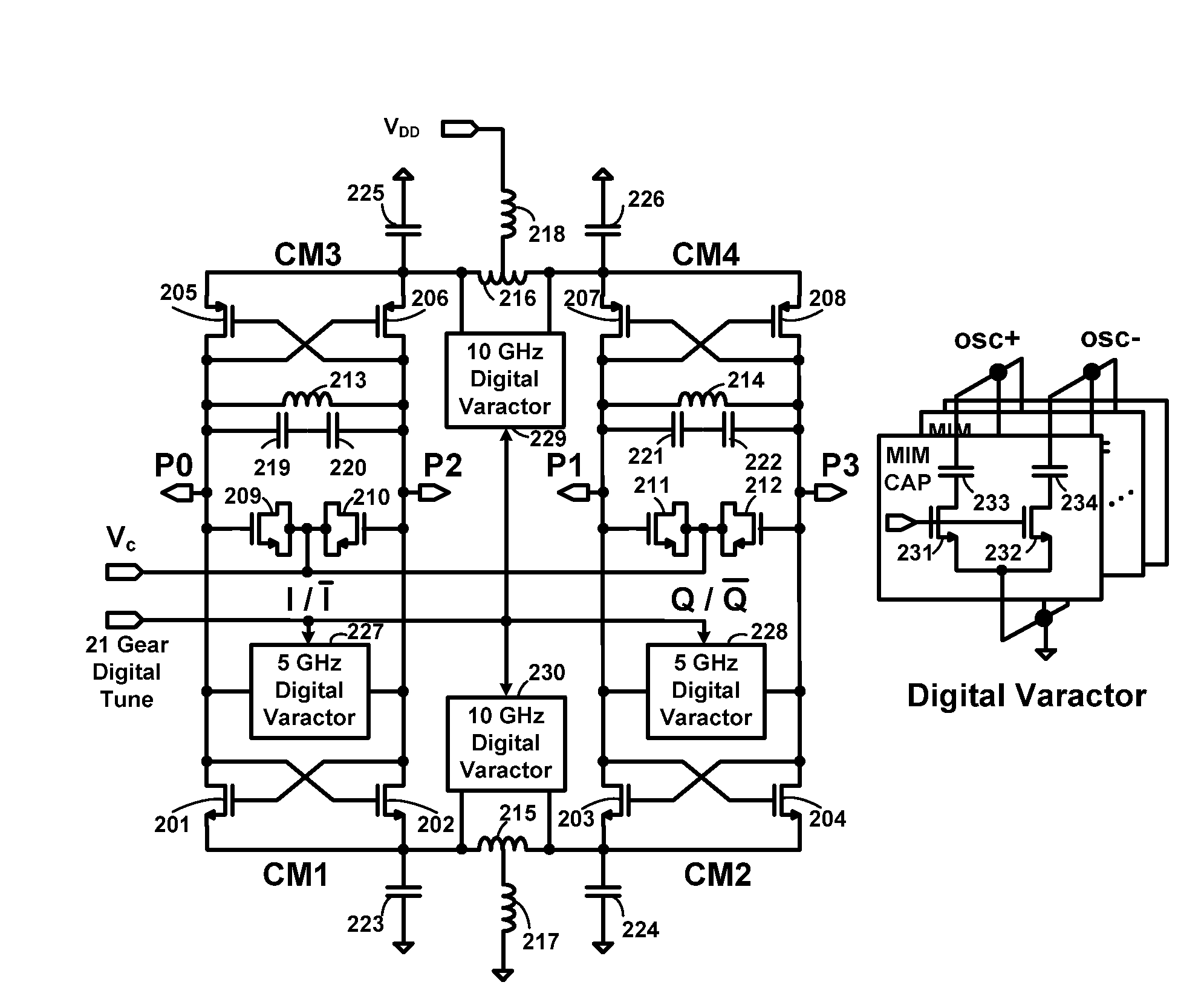
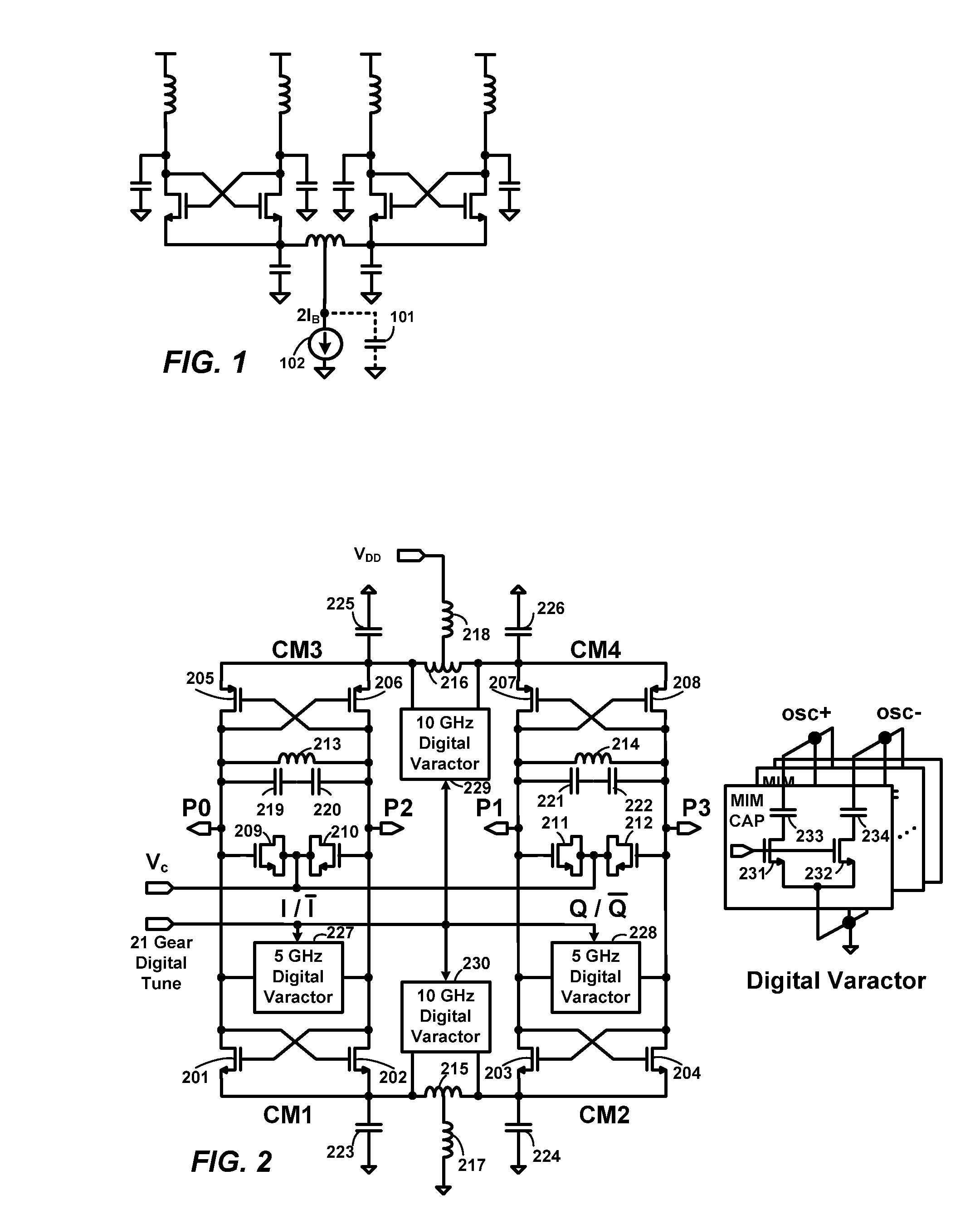
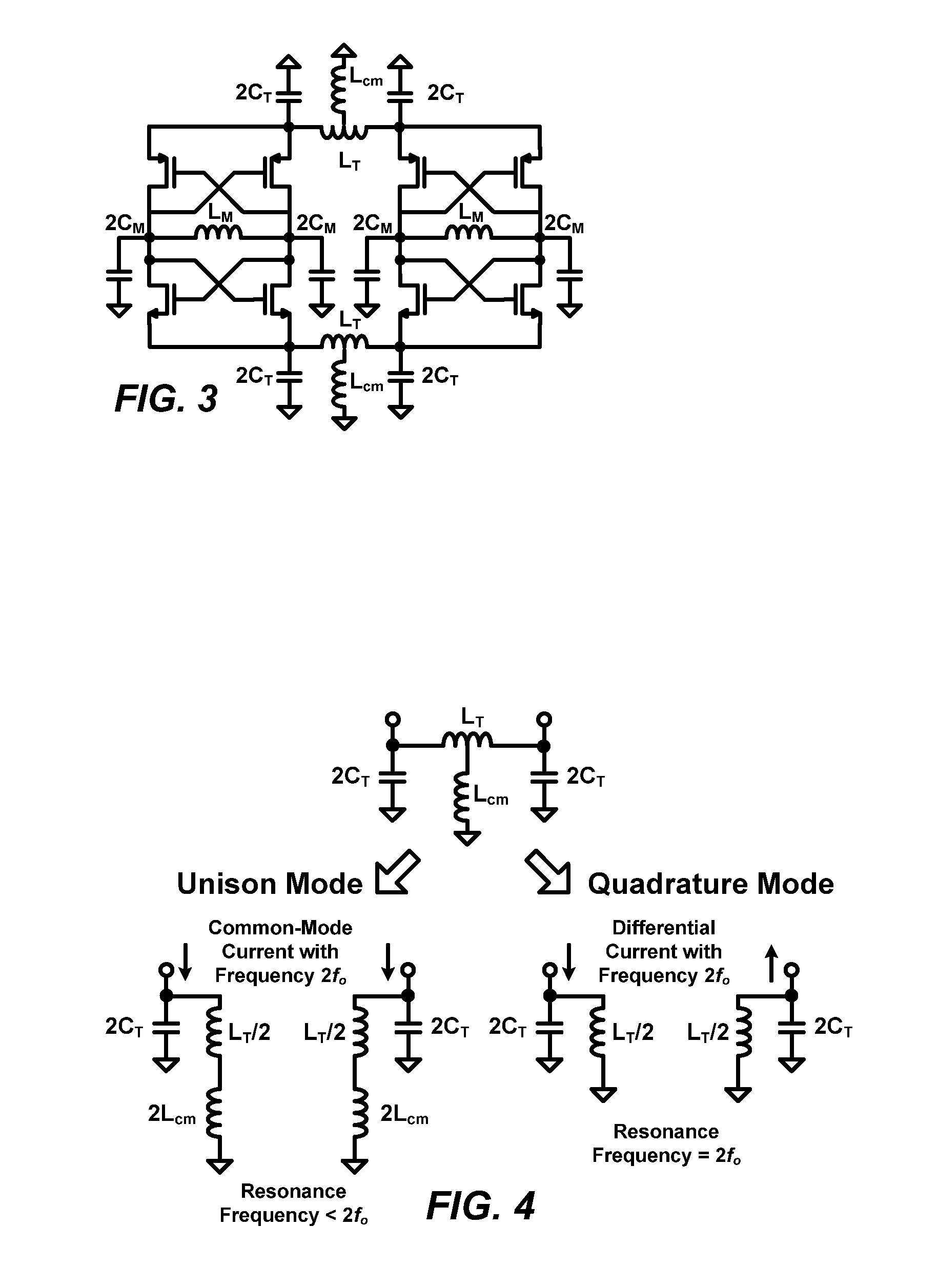
[0041]The proposed QVCO utilizing tail-tank coupling is shown in FIG. 2, and its equivalent model for analysis is shown in FIG. 3. Two copies of complementary LC-VCOs are combined together at NMOS and PMOS tail nodes by two separate LC tanks. Whenever a transistor in a cross-coupled pair enters the triode region, the tail node waveform is forced to follow the main tank waveform. Two transistors in a cross-coupled pair take turns operating in the deep-triode region, and thus, oscillation waveforms at frequency 2fo are created at the tail nodes. There are two possible modes of oscillation: The two complementary LC-VCOs can either oscillate in unison to produce the same output phases or they can produce quadrature output phases as described in A. Mirzaei and A. A. Abidi, “Analysis of oscillators locked by large injection signals: generalized Adler's equation and geometrical interpretation,” in Proc. IEEE Custom Integrated Circuits Conf., September 2006, p...


PUM


Abstract

A tail-tank coupling technique combines two complementary differential LC-VCOs to form a quadrature LC-VCO. The technique reduces phase noise by providing additional energy storage for noise redistribution and by cancelling noise injected by transistors when they operate in the triode region. The resulting noise factor is close to the theoretical minimum 1+γ, similar to a differential LC-VCO driven by an ideal noiseless current source. However, its figure-of-merit is higher, due to the absence of voltage head-room being consumed by a current source. The optimal ratio of tail-tank capacitor to main-tank capacitor for minimizing phase noise is approximately 0.5. The method can be extended to combine any even number of LC tanks resonating at fo and 2fo to form an integrated oscillator producing quadrature phase at frequency fosc and differential output at 2fosc.

Description

[0001]This application claims the benefit of and priority of U.S. Provisional Patent Application Ser. No. 60 / 870,350, entitled “Low Phase-Noise Quadrature Phase Oscillator” by Chih-Wei Yao and Alan N. Willson, Jr., filed on Dec. 15, 2006.BACKGROUND OF THE INVENTION[0002]1. Field of the Invention[0003]The present invention relates generally to an oscillator, and more particularly, to a low phase-noise oscillator.[0004]2. Description of the Related Art[0005]Quadrature phase clock generation finds applications in many communication systems. For RF front-ends, quadrature phase is required for image rejection receivers and for down-converting RF / IF signals to baseband. For high speed clock and data recovery (CDR) systems, quadrature phase is required for half-rate phase detection, phase-interpolation, and frequency detection.[0006]One of three approaches can be adopted to generate quadrature phase: First, a quadrature VCO (QVCO) can be used. Second, a divide-by-two circuit can generate q...

Claims


Application Information

Patent Timeline
Patent Type & Authority Applications(United States)
IPC IPC(8): H03B27/00H03B5/12
CPCH03B27/00H03B5/1228H03B5/1253H03B5/1215H03B2200/0074H03B5/1212H03L7/24
Inventor YAO, CHIH-WEIWILLSON, ALAN NEIL
Owner WILLSON ALAN N JR
Why Eureka
Try Eureka