Liftable bowl basket
A technology of bowl basket and lifting mechanism, which is applied in the direction of tableware washing machine/rinsing machine, cleaning equipment, household utensils, etc., which can solve the problems of inconvenient use, low installation position of dishwasher, poor user experience, etc. problems, to achieve the effect of easy placement, space saving, and labor intensity reduction
- Summary
- Abstract
- Description
- Claims
- Application Information
AI Technical Summary
Problems solved by technology
Method used
Image

Examples
Embodiment 1
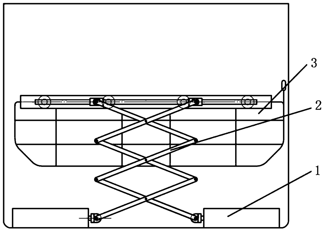
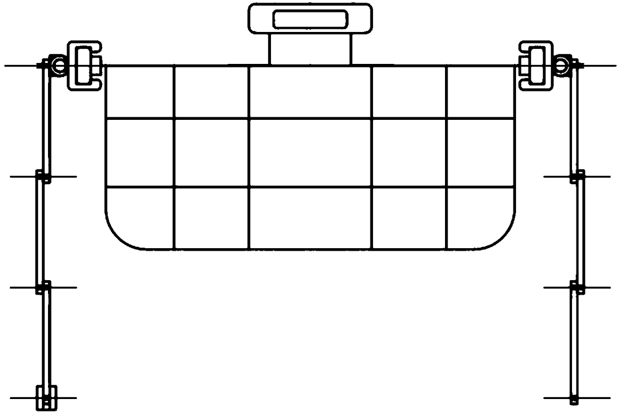
[0022] This embodiment discloses a liftable bowl basket, its specific structure is as follows: Figure 1-Figure 2 shown.
[0023] Such as figure 1 As shown, the liftable bowl basket of this embodiment is mainly composed of a bowl basket body 3 , a folding frame 2 and an electric push rod 1 . The folding frame 2 includes two groups of connecting rods, each group of connecting rods is hinged by several connecting rod units sequentially, and the two groups of connecting rods cross each other and are hinged at the intersections. The upper edge of the bowl basket body 3 has a chute, and the upper end of each group of connecting rods can slide in the chute. Electric push rod 1 also has two, and each electric push rod is respectively hinged the lower end of a group of connecting rods.
[0024] When lifting the bowl basket, each electric push rod is extended or shortened in reverse, so that the lower ends of the two sets of connecting rods move in opposite directions, so that the f...
Embodiment 2
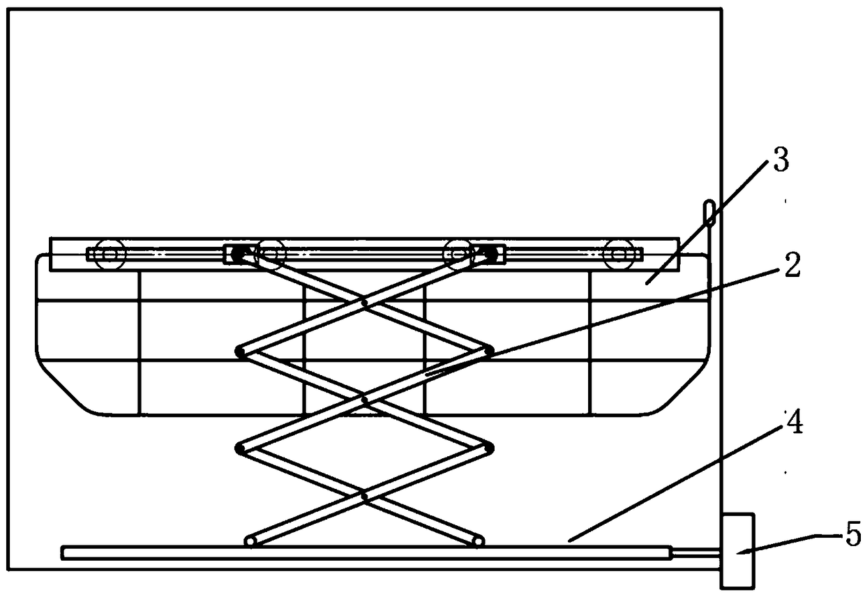
[0028] For another embodiment of the present invention, see image 3 , In this embodiment, the electric push rod 1 is replaced by a worm gear structure composed of a motor 5 and a worm gear 4, and the lower ends of each set of connecting rods are respectively hinged on the worm gear structure. When lifting the bowl basket, the motor 5 drives the worm gear 4 to act, so that the lower ends of the two groups of connecting rods hinged on the worm gear structure move in opposite directions, and the lifting of the bowl basket body 3 can also be realized.
Embodiment 3
[0030] For another embodiment of the present invention, see Figure 4 , in this embodiment, no longer use the folding frame 2 and its driving mechanism, but directly adopt the electric telescopic push rod that is driven and can expand and contract in the vertical direction. The electric telescopic push rod is composed of three telescopic rods. The upper end of the electric telescopic push rod is directly connected to the bowl body, and the lower end is connected to the driving mechanism of the electric telescopic push rod. When the driving mechanism drives the electric telescopic push rod to expand and contract, the bowl basket body 3 will also rise and fall accordingly.
PUM
 Abstract
Description
Claims
Application Information
 - R&D
- Intellectual Property
- Life Sciences
- Materials
- Tech Scout
- Unparalleled Data Quality
- Higher Quality Content
- 60% Fewer Hallucinations
Browse by: Latest US Patents, China's latest patents, Technical Efficacy Thesaurus, Application Domain, Technology Topic, Popular Technical Reports.
© 2025 PatSnap. All rights reserved.Legal|Privacy policy|Modern Slavery Act Transparency Statement|Sitemap|About US| Contact US: help@patsnap.com