Drive device for assisting in turnover of toy car
A technology for driving devices and toy cars, which can be used in toy cars, toys, entertainment, etc., and can solve problems such as inconvenient use
- Summary
- Abstract
- Description
- Claims
- Application Information
AI Technical Summary
Problems solved by technology
Method used
Image
Examples
Embodiment 1
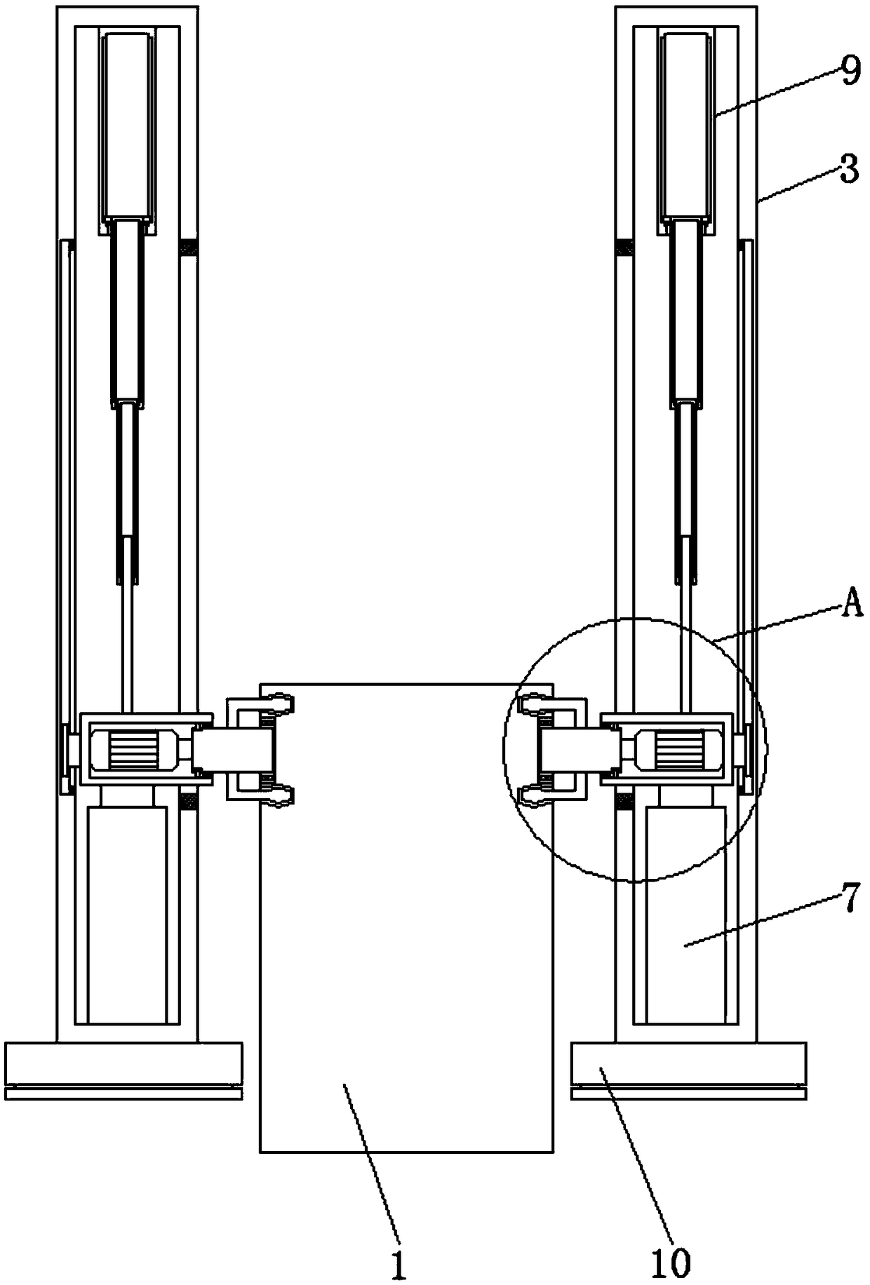
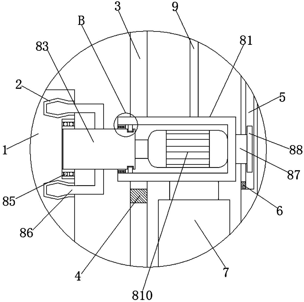
[0025] Such as Figure 1-3 As shown, a driving device for assisting a toy car to turn over includes a toy car 1, the top of the toy car 1 is symmetrically provided with connecting grooves 2, and the two sides of the toy car 1 are symmetrically provided with supporting columns 3, and the supporting columns 3 on both sides are arranged symmetrically. A first opening is symmetrically opened in the middle of the opposite side, and a first track plate 4 is fixedly connected to the first opening, and a chute 5 is opened symmetrically in the middle of the other side of the supporting column 3, and the notch of the chute 5 is fixedly connected with a The second track plate 6 is fixedly connected with the first electric push rod 7 at the center of the inner wall bottom of the support column 3, and the drive mechanism 8 is arranged at the center of the inner cavity of the support column 3, and is fixedly connected with the second electric push rod at the center of the inner wall top of t...
Embodiment 2
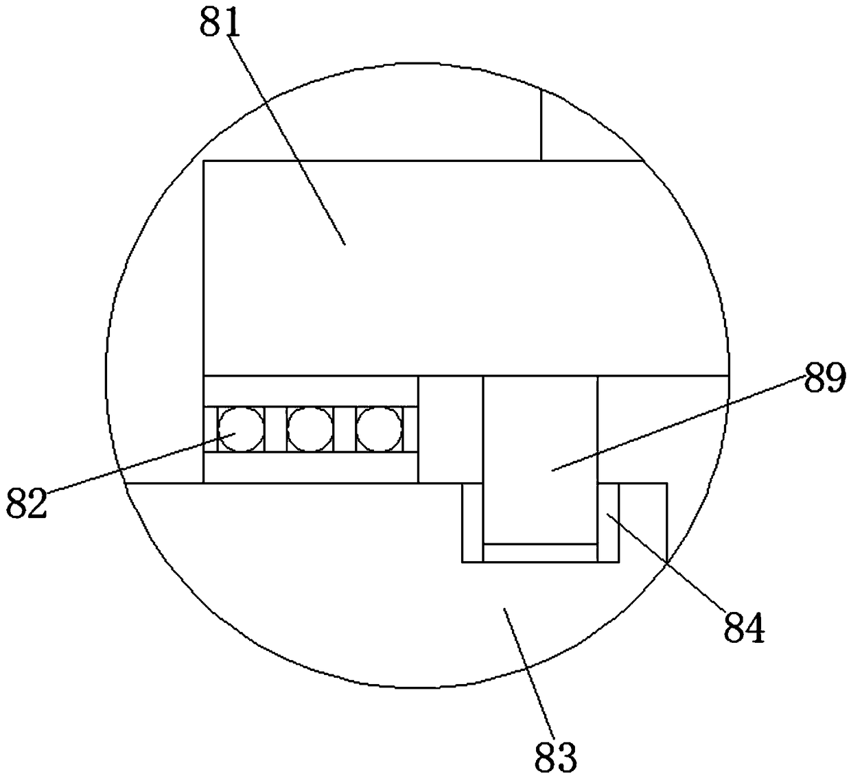
[0027] On the basis of Embodiment 1, the driving mechanism 8 includes a pressure-bearing column 81, a second opening is opened in the middle of the opposite side of the pressure-bearing column 81 on both sides, and a first bearing 82 is fixedly connected to the second opening. The pressure-bearing column 81 A rotating shaft 83 is arranged in the middle of one side, and an annular limit groove 84 is provided at one end of the rotating shaft 83 close to the pressure bearing column 81. The other end of the rotating shaft 83 is sleeved with a second bearing 85, and the middle part of the top and bottom of the rotating shaft 83 A connecting rod 86 is fixedly connected symmetrically, and a connecting column 87 is fixedly connected to the center of the other side of the pressure-bearing column 81. The end of the connecting column 87 away from the pressure-bearing column 81 is fixedly connected to a pressure-bearing plate 88. One of the inner chambers of the pressure-bearing column 81 ...
Embodiment 3
[0029] On the basis of Embodiments 1 and 2, the center of the first track plate 4 is provided with a first through hole communicating with its left and right sides, and the center of the second track plate 6 is provided with a second through hole communicating with its left and right sides. One end of the first electric push rod 7 away from the inner wall of the support column 3 is fixedly connected to the other side of the bottom of the pressure bearing column 81, and the end of the second electric push rod 9 away from the inner wall of the support column 3 is fixedly connected to the other side of the top of the pressure bearing column 81 side.
PUM
 Abstract
Description
Claims
Application Information
 - R&D
- Intellectual Property
- Life Sciences
- Materials
- Tech Scout
- Unparalleled Data Quality
- Higher Quality Content
- 60% Fewer Hallucinations
Browse by: Latest US Patents, China's latest patents, Technical Efficacy Thesaurus, Application Domain, Technology Topic, Popular Technical Reports.
© 2025 PatSnap. All rights reserved.Legal|Privacy policy|Modern Slavery Act Transparency Statement|Sitemap|About US| Contact US: help@patsnap.com


