
The installation structure of the movable module of the power storage battery pack used in the airtight hybrid electric locomotive

A power battery and hybrid power technology, which is applied in the field of installation structure of power battery packs for hybrid locomotives, can solve the problems of low fastness of installation and fixation, lack of safety protection, heavy workload, etc., and achieves convenient lifting and installation, and improved Temperature control efficiency and the effect of reducing life loss

Active Publication Date: 2020-01-14
CRRC ZIYANG CO LTD
View PDF7 Cites 0 Cited by
  • Summary
  • Abstract
  • Description
  • Claims
  • Application Information

AI Technical Summary

Problems solved by technology

In traditional hybrid locomotives, the battery packs are distributed in multiple series-connected battery pack slots. During maintenance and overhaul, each battery pack is installed or disassembled one by one, which requires a lot of work, time-consuming and laborious; and the fastness of the battery pack installation is low. , under the current demand for high-speed operation, it is vulnerable to impact loads from all directions and lacks safety protection; in addition, the battery pack needs a relatively independent environment to avoid interference from adverse environmental factors such as water and heat, and ensure the normal operation and use of the locomotive life
However, none of the storage battery packs of current hybrid electric locomotives can solve the above problems

Method used


Image

  • The installation structure of the movable module of the power storage battery pack used in the airtight hybrid electric locomotive
  • The installation structure of the movable module of the power storage battery pack used in the airtight hybrid electric locomotive
  • The installation structure of the movable module of the power storage battery pack used in the airtight hybrid electric locomotive

Examples


Embodiment 1

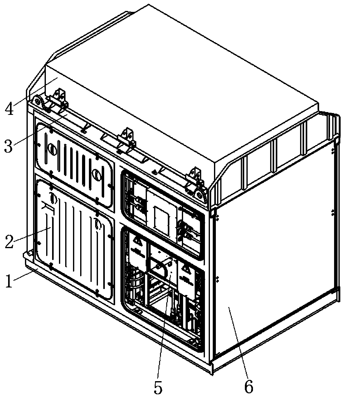
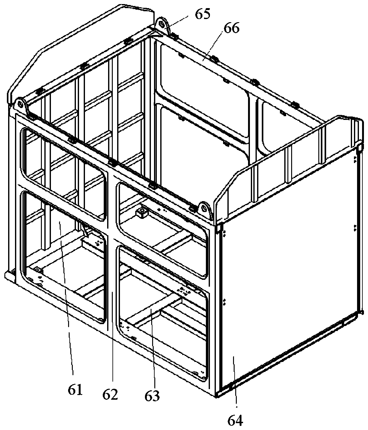
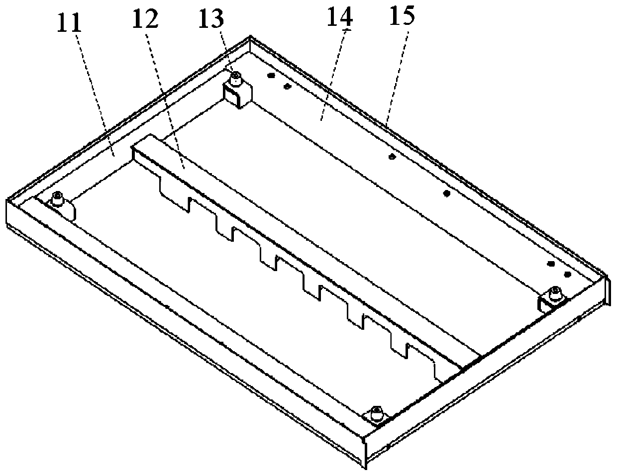
[0029] refer to Figure 1~5 , a movable module installation structure of a power battery pack for a hybrid electric locomotive, comprising a module mounting frame 1 and a battery pack movable module mounted thereon, the module mounting frame 1 being welded on the upper plane of the locomotive chassis, and the movable module mainly comprising The battery room steel structure 6 and the power battery pack 5 installed in it, the left and right sides of the battery room steel structure 6 are provided with sealed inspection doors 2, and the upper plane of the battery room steel structure 6 and the power battery pack 5 is installed with movable bolts The air-conditioning mounting frame 3 is sealed with a sealing strip. The battery air-conditioning unit 4 is installed on the top of the air-conditioning mounting frame 3 and is also sealed with a sealing strip. The air outlet of the battery air-conditioning unit 4 is inside the module.

[0030] The air conditioner installation frame 3 i...


PUM


Abstract

Disclosed is a power accumulator battery activity module mounting structure for a closed hybrid power locomotive. The structure comprises a module mounting frame (1), an accumulator battery room steel structure (6), a power accumulator battery (5), and access doors (2); the module mounting frame (1) is welded and fixedly provided on the upper plane of a base frame of the locomotive; the accumulator battery room steel structure (6) is movably mounted on the module mounting frame (1) by means of bolts; the power accumulator battery (5) is movably mounted in the accumulator battery room steel structure (6) by means of the bolts; the access doors (2) are mounted on two sides of the accumulator battery room steel structure (6); an accumulator battery air conditioning unit (4) is mounted at the top of the accumulator battery room steel structure (6) in a sealing manner. In the power accumulator battery activity module mounting structure for the hybrid power locomotive, an accumulator battery activity module can be separately hoisted and mounted, so that a large amount of time in the maintenance and repair can be saved; in addition, the power accumulator battery activity module mounting structure is safe and firm, and strong in anti-vibration impact and external interference capabilities.

Description

technical field [0001] The invention belongs to the field of locomotives and vehicles, and in particular relates to a movable module installation structure of a closed power storage battery pack for hybrid electric locomotives. Background technique [0002] The power system of a hybrid locomotive includes a battery pack and a diesel generator set. The diesel generator set charges the battery and provides additional energy when the locomotive needs high power. Compared with the traditional locomotive, the hybrid locomotive can save a lot of fuel. [0003] The battery pack is used as an energy storage and is controlled in parallel with the diesel generator set. This device can not only provide energy for the driving device, but also be used to drive the auxiliary transmission device, and can also be used to charge the battery. It plays a key role in the locomotive. In traditional hybrid locomotives, the battery packs are distributed in multiple series-connected battery pack sl...

Claims


Application Information

Patent Timeline
Patent Type & Authority Patents(China)
IPC IPC(8): B61C3/02B61C17/06
CPCB61C3/02B61C17/06Y02T30/00
Inventor 景松柏姚金梅孟玉发李柯陈传彬任聪熊明彬唐念
Owner CRRC ZIYANG CO LTD
Learn More