A method for smoothing and shaping the nozzle profile of a high-enthalpy wind tunnel
A smoothing and nozzle technology, applied in the field of aerodynamics, can solve problems such as the inability to realize spline free control, and achieve the effect of eliminating local fluctuations
- Summary
- Abstract
- Description
- Claims
- Application Information
AI Technical Summary
Problems solved by technology
Method used
Image
Examples
Embodiment 1
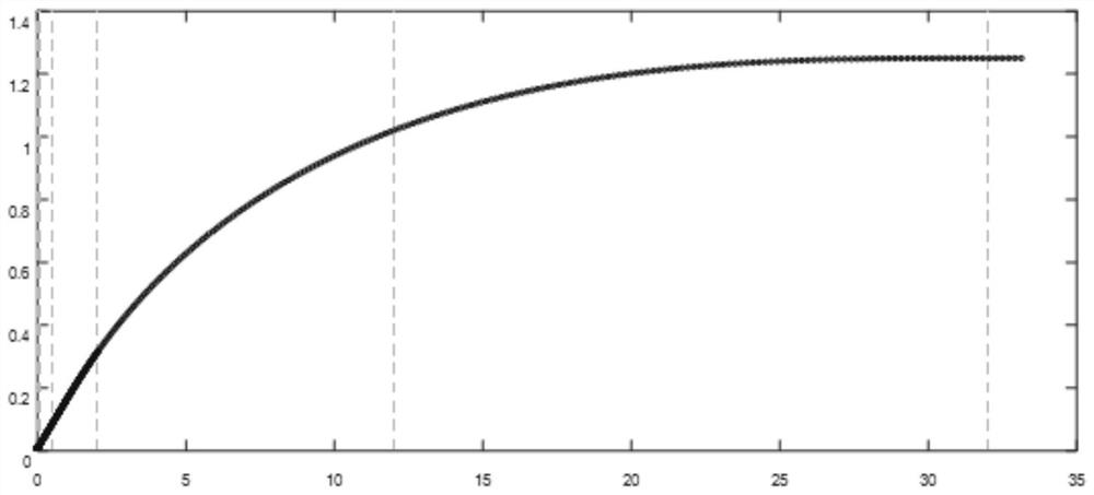
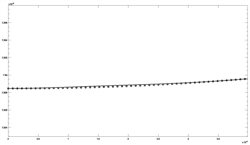
[0143] figure 1 An overview of the reference point of the nozzle profile and its smoothing profile, figure 2 is the partial graph of the starting end, figure 2 The circle in is the reference point of the model line, which is the calculation result of the unbalanced fluid, and the vertical line indicates the position of the control node, figure 1 The curve in is the smoothed and shaped nozzle profile, that is, the controllable Hermitian spline that satisfies the conditions.
[0144] It can be seen from this figure that the control nodes can be freely rebuilt according to the needs, so as to realize more precise control on the throat section, segmental connection points, etc., and the spline curve obtained by using the method of the present invention is generally given by the calculation of the non-equilibrium fluid. The reference points are very close in general, and can be seen after partial zoom-in. The stereotyped curve eliminates the local fluctuation of the reference p...
Embodiment 2
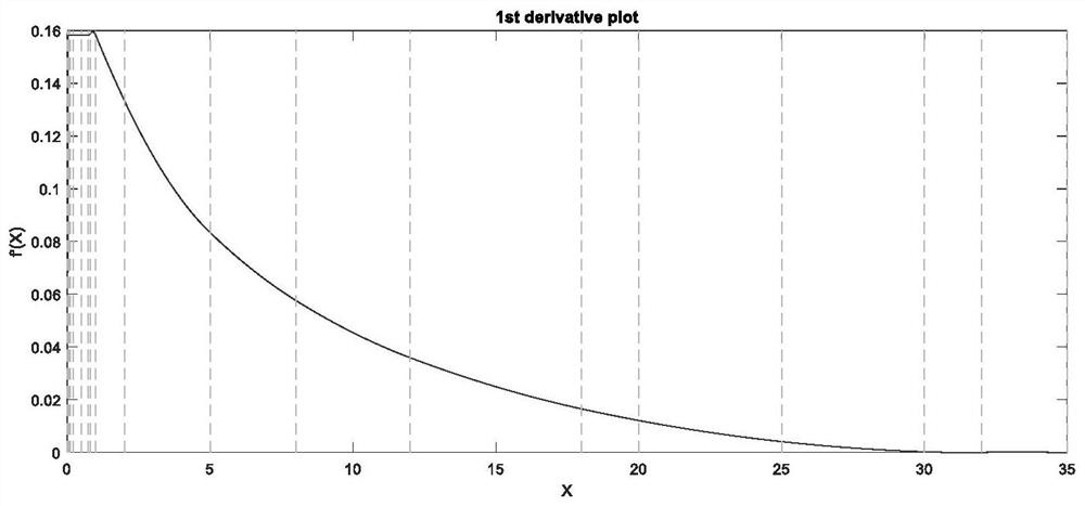
[0147] Such as Figure 1 to Figure 12 As shown, the length of the entire nozzle profile can reach more than 30 meters, and can be divided into three sections: the key section of the starting end (throat), which is generally very short. In this example, the horizontal length is 36.53 mm. The unbalanced fluid calculation gives The position of the reference point is as Figure 7 shown.
[0148] The second section is a straight section. In this example, the horizontal length is about 0.7 meters, and the reference point position is as follows Figure 8 shown.
[0149] The third section is the main part of the nozzle, which is relatively long in length, more than 30 meters in this example, and the position of the reference point is as follows Figure 9 shown.
[0150] The reference points given by the non-equilibrium fluid calculation are partially enlarged, and it can be seen that there are local fluctuations in these points. According to these reference points to smooth the n...
Embodiment 3
[0154] There are 21 reference points (here only to demonstrate the effect of the method, the actual number of reference points is 10 3 ~10 6 ), the coordinates are as follows:
[0155]
[0156]
[0157] It is necessary to construct a controllable Hermitian spline that meets the requirements, which can be operated as follows:
[0158] 5 evenly distributed control points, the second-order continuity is guaranteed by default, and the curve passes through all reference points as much as possible, such as Figure 13 shown;
[0159] Fine control: Add two control points (the abscissas are 1.8, 3.2) near the second control point (the abscissa is 2.5), such as Figure 14 shown;
[0160] Continue to increase hard constraints: the curve increases monotonically throughout the interval, such as Figure 15 shown;
[0161] Continue to add hard constraints: the curve must pass through a certain point in the reference point, such as the 11th point, that is (5,0.6192), such as Fig...
PUM
 Abstract
Description
Claims
Application Information
 - R&D
- Intellectual Property
- Life Sciences
- Materials
- Tech Scout
- Unparalleled Data Quality
- Higher Quality Content
- 60% Fewer Hallucinations
Browse by: Latest US Patents, China's latest patents, Technical Efficacy Thesaurus, Application Domain, Technology Topic, Popular Technical Reports.
© 2025 PatSnap. All rights reserved.Legal|Privacy policy|Modern Slavery Act Transparency Statement|Sitemap|About US| Contact US: help@patsnap.com


