Smooth fixing method for jet pipe molded line of high-enthalpy wind tunnel

A smoothing and nozzle technology, applied in the field of aerodynamics, can solve problems such as the inability to realize spline free control, and achieve the effect of eliminating local fluctuations

Active Publication Date: 2019-03-08
INST OF MECHANICS - CHINESE ACAD OF SCI
View PDF5 Cites 3 Cited by
  • Summary
  • Abstract
  • Description
  • Claims
  • Application Information

AI Technical Summary

Problems solved by technology

[0003] The existing smoothing and shaping methods either perform global fitting or interpolation, or perform point-by-point segmental local fitting or interpolation, which cannot realize the free control of splines and meet the above 7 requirements

Method used


Image

  • Smooth fixing method for jet pipe molded line of high-enthalpy wind tunnel
  • Smooth fixing method for jet pipe molded line of high-enthalpy wind tunnel
  • Smooth fixing method for jet pipe molded line of high-enthalpy wind tunnel

Examples


Embodiment 1

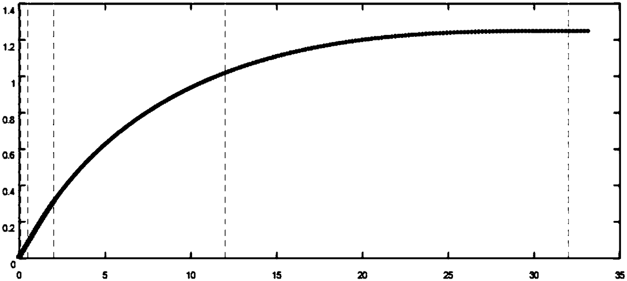
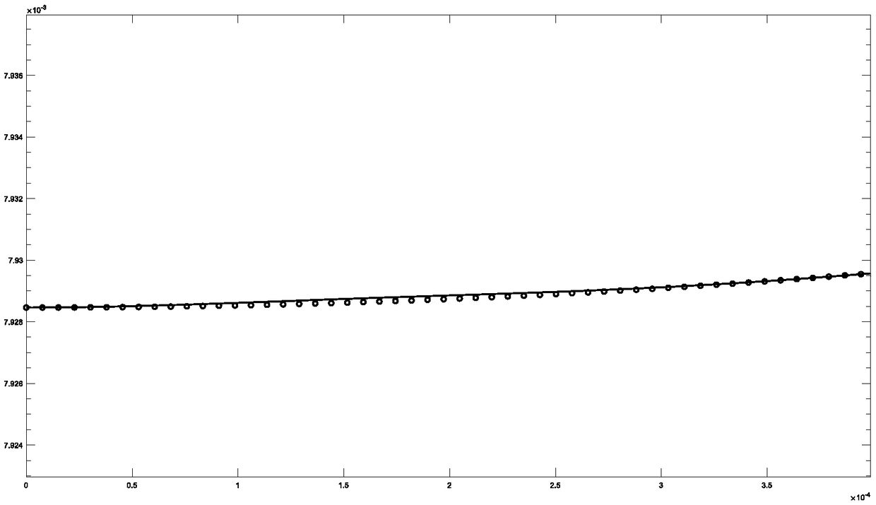
[0143] figure 1 An overview of the reference point of the nozzle profile and its smoothing profile, figure 2 is the partial graph of the starting end, figure 2 The circle in is the profile line reference point, which is the calculation result of unbalanced fluid, and the vertical line indicates the position of the control node, figure 1 The curve in is the smoothed and shaped nozzle profile, that is, the controllable Hermite spline that satisfies the conditions.

[0144] It can be seen from this figure that the control nodes can be freely rebuilt according to the needs, so as to realize more precise control on the throat section, segment connection points, etc., and the spline curve obtained by using the method of the present invention is generally compared with the non-equilibrium fluid calculation. The reference points are very close in general, and can be seen after partial zoom-in. The stereotyped curve eliminates the local fluctuation of the reference point and other ...

Embodiment 2

[0147] Such as Figure 1 to Figure 12 As shown, the length of the entire nozzle profile can reach more than 30 meters, and can be divided into three sections: the key section of the starting end (throat), which is generally very short. In this example, the horizontal length is 36.53 mm. The position of the reference point is as Figure 7 shown.

[0148] The second section is a straight section. In this example, the horizontal length is about 0.7 meters, and the reference point position is as follows Figure 8 shown.

[0149] The third section is the main part of the nozzle, which is relatively long in length, more than 30 meters in this example, and the reference point position is as follows Figure 9 shown.

[0150] The reference points given by the non-equilibrium fluid calculation are partially enlarged, and it can be seen that there are local fluctuations in these points. According to these reference points to smooth the nozzle profile, the difficulty lies in how to r...

Embodiment 3

[0154] There are 21 reference points (here only to demonstrate the effect of the method, the actual number of reference points is 10 3 ~10 6 ), the coordinates are as follows:

[0155]

[0156]

[0157] It is necessary to construct a controllable Hermitian spline that meets the requirements, which can be operated as follows:

[0158] 5 uniformly distributed control points, the second-order continuity is guaranteed by default, and the curve passes through all reference points as much as possible, such as Figure 13 shown;

[0159] Fine control: add two control points (the abscissas are 1.8, 3.2) near the second control point (the abscissa is 2.5), such as Figure 14 shown;

[0160] Continue to increase hard constraints: the curve increases monotonically throughout the interval, such as Figure 15 shown;

[0161] Continue to add hard constraints: the curve must pass through a certain point in the reference point, such as the 11th point, that is (5,0.6192), such as ...


PUM


Abstract

The invention discloses a smooth fixing method for a jet pipe molded line of a high-enthalpy wind tunnel. The method comprises the following steps that S100) control nodes are reconstructed, and the number of nodes in a detailed position is higher than that of nodes in a normal position; S200) soft and hard constraints are solved successively; and S300) the soft and hard constraints are calculatedin a combined way to obtain a controllable Hermite spline, an obtained spline curve totally approaches a total reference point body provided by nonequilibrium fluid calculation, and is visible afterlocal amplification, and a fixing curve eliminates problems including local fluctuation of reference points. Thus, free control needed by jet-pipe molded line fixing can be realized.

Description

technical field [0001] The invention relates to the technical field of aerodynamics, in particular to a method for smoothing and shaping the nozzle profile of a high-enthalpy wind tunnel. Background technique [0002] The nozzle is the core component of the wind tunnel, which directly determines the flow field quality of the wind tunnel. The key to nozzle design lies in the optimization of its profile. Especially for high-enthalpy wind tunnels, the nozzle design needs to be calculated with the help of non-equilibrium fluid. The reference point of the given nozzle profile has certain fluctuations and numerical errors. The throat The section curve changes greatly, and finer control must be achieved. At the same time, considering the replaceability of the throat section of the nozzle, the profile design must be carried out in sections, and the connections between sections must also meet certain physical requirements. In fact, , in order to ensure the performance of the nozzle,...

Claims


Application Information

Patent Timeline
Patent Type & Authority Applications(China)
IPC IPC(8): G01M9/04
CPCG01M9/04
Inventor 罗长童汪运鹏姜宗林
Owner INST OF MECHANICS - CHINESE ACAD OF SCI
Why Eureka
Try Eureka